How to cross compile and sign Windows EXE on Linux with Yubikey token

I recently obtained a new code signing certificate used to sign the Windows version of Teensy’s software. Because key storage rules have changed, and very little information currently exists for use in a cross compile workflow, I decided to write this article.

The basic concept is you wish to compile software for Windows, from the comfort of your Linux machine. The Windows EXE file needs to be properly signed, so users see “Verified Publisher” and Microsoft Defender SmartScreen will (eventually) learn your application is safe.

These steps were performed on Ubuntu 22.04. Other Linux distributions can very likely also work.

Buying a Code Signing Certificate

Before June 2023, obtaining a code signing cert was simpler and less expensive. You would create a private key and use it to send a certificate signing request (CSR). After verifying your identity, the certificate authority would send you the certificate file.

Signing a Windows EXE file requires these 2 items, a secret key and a certificate issued by one of the certificate authority companies Microsoft trusts. Previously it was just 2 files on your computer, or a single “P12” format file which can hold both.

Since June 2023, your secret key must either be stored inside a hardware token and/or stored on the certificate authority’s cloud service. Supposedly this is more secure.

It is also much more expensive! As with buying anything, shop around. Prices vary and change. As of March 2024, the best price I found was at SSL.com. This article isn’t sponsored or affiliated with SSL.com in any way. They simply had the best (least bad) price in March 2024. Pricing for “OV” was $110 per year for 3 years, and $250 for the hardware key. The actual hardware has $80 retail price when blank from Yubico.

If you choose another certificate authority, you might contact them to confirm the hardware key is Yubikey FIPS. Theoretically other hardware keys might exist, if not today then at some point in the future, and you would want to confirm whether the hardware they send works with Linux and libengine-pkcs11-openssl.

SSL.com also offers a cloud service which eliminates the need for a hardware key, but its least expensive tier is $20/month. That’s almost as much as the Yubikey FIPS hardware, repeated every year! Worse year, that low tier offers only 20 signatures per month. Teensy’s software has several signed EXE files. Merely building a few beta tests could mean needing the next tier.

After you’ve paid, the certificate authority will verify your identity. For “OV” level, the verification is so simple that the price and complexity of needing a hardware token feels rather wasteful. Nonetheless, to get Windows “Verified Publisher” this is the process.

Then all you can do is wait for your Yubikey token to arrive.

Collect Critically Important Data

Your Yubikey FIPS token will arrive initialized with 2 passwords, called PIN and PUK. Your first step is to obtain these 2 passwords.

From SSL.com, my Yubikey came with an 8 digit serial number, printed on a label and also on the key. On the SSL.com website order summary, under “CERTIFICATE DETAILS” -> “physical tokens” was an “activate” link. Clicking it brings up a dialog box to enter the 8 digit serial number. After entering the serial number, the PIN and PUK passwords appeared.

Other certificate authorities will likely work differently, but all Yubikey FIPS use these PIN and PUK passwords for access to the key. You must get the PIN and PUK passwords the certificate authority used. If the PIN is entered incorrectly 3 times, the key becomes locked. The PUK password lets you assign a new PIN password. If PUK is incorrect 3 times, the hardware becomes unusable! Make sure you have the correct PIN and PUK before using your key.

You will also need the certificate data. On the SSL.com I found this on the order summary page under “END ENTITY CERTIFICATES”. It begins “—–BEGIN CERTIFICATE—–“, has a couple dozen lines of base64 encoded data, and ends with “—–END CERTIFICATE—–“. Save this to a file. Any name is ok, I named it “mycert.pem”.

Install Software

Fortunately Ubuntu 22.04 has all the required software as packages. Use these commands install everything demonstrated in this article.

sudo apt install yubikey-manager osslsigncode ykcs11 libengine-pkcs11-openssl
sudo apt install gcc-mingw-w64-i686
sudo apt install wine

You only need the (large) wine package if you want to run your freshly compiled EXE on Linux.

Check Yubikey Hardware

Now you’re ready to plug in your Yubikey and check it. First run this command:

ykman list

You should see it detect your Yubikey and print basic info. The 8 digit serial number should appear.

YubiKey 5 NFC FIPS (5.4.3) [OTP+FIDO+CCID] Serial: 00000000

Type this command to check the keys stored:

ykman piv info

You should see results like this, but with actual serial numbers instead of zeros.

PIV version: 5.4.3
PIN tries remaining: 3/3
Management key algorithm: TDES
Management key is stored on the YubiKey, protected by PIN.
CHUID: 0000000000000000000000000000000000000000000000000000000000000000000000000000000000000000000000000000000000000000000000
CCC:   No data available.
Slot 84:
        Algorithm: ECCP384
        Subject DN: CN=SSL.com Code Signing Intermediate CA ECC R2,O=SSL Corp,L=Houston,ST=Texas,C=US
        Issuer DN: CN=SSL.com Root Certification Authority ECC,O=SSL Corporation,L=Houston,ST=Texas,C=US
        Serial: 00000000000000000000000000000000000000
        Fingerprint: 0000000000000000000000000000000000000000000000000000000000000000
        Not before: 2019-03-07 19:35:47
        Not after: 2034-03-03 19:35:47
Slot 9a:
        Algorithm: ECCP384
        Subject DN: CN=PJRC.COM\, LLC,O=PJRC.COM\, LLC,L=Sherwood,ST=Oregon,C=US
        Issuer DN: CN=SSL.com Code Signing Intermediate CA ECC R2,O=SSL Corp,L=Houston,ST=Texas,C=US
        Serial: 00000000000000000000000000000000000000
        Fingerprint: 0000000000000000000000000000000000000000000000000000000000000000
        Not before: 2024-03-04 15:51:07
        Not after: 2027-03-04 15:51:07

The “PIN tries remaining” is particularly important. If you enter the PIN password incorrectly 3 times, the hardware becomes locked. Best to download the graphical YubiKey Managers software from Yubico’s website, and use it to set a new PIN with the PUK password. However, 3 wrong tries with PUK locks the hardware completely. Unlocking requires deleting the keys you paid $250 to get.

Compile a Windows EXE program

Create a file “hello.c” with any simple C program.

#include <stdio.h>
int main() {
    printf("Hello World\n");
    return 0;
}

Use these commands to compile and run the code.

i686-w64-mingw32-gcc -Os -s -o hello.exe hello.c
wine hello.exe

Check Yubikey PKCS11 module pathname

The default PKCS11 module pathname is /usr/lib/x86_64-linux-gnu/libykcs11.so

If you run Linux on hardware other than x86-64, such as Raspberry Pi, or if you use a different Linux distribution, the pathname may differ. On Ubuntu, you can use dpkg to see all the files the ykcs11 package installed.

dpkg -L ykcs11
ls -l /usr/lib/x86_64-linux-gnu/libykcs11.so
ls -l /usr/lib/x86_64-linux-gnu/libykcs11.so.2
ls -l /usr/lib/x86_64-linux-gnu/libykcs11.so.2.2.0

Sign your hello.exe file

To sign your freshly compiled EXE file, run osslsigncode with these parameters. If your PKCS11 module pathname is different, replace it as needed.

rm -f hello2.exe
osslsigncode sign -h sha2 -pkcs11module /usr/lib/x86_64-linux-gnu/libykcs11.so -certs mycert.pem -key 'pkcs11:pin-value=XXXXXXXX' -ts http://ts.ssl.com -in hello.exe -out hello2.exe

If hello2.exe already exists, osslsigncode isn’t very smart and will show confusing errors. Best to make sure it’s deleted before running osslsigncode.

Your new hello2.exe file is a signed copy. When copied to a Windows computer, right click and view Properties. It should have a Digital Signatures tab. Clicking Details should show the signature info.

Microsoft Defender SmartScreen

Unfortunately, unless you purchased the most expensive “EV” type certificate, your signature using a brand new key will not yet have a reputation with SmartScreen. Windows users will see “isn’t commonly downloaded”.

Eventually as more people download and use your software, SmartScreen will begin to trust it.

Feedback

If you have questions or feedback, please post on this forum thread.

Especially if you know of certificate authorities offers better prices, please share!

Teensy 3.2 End Of Life

With great sadness, we’re discontinuing Teensy 3.2.

Teensy 4.0 and 4.1 will continue.  We’re able to get the new 600 MHz chips in sufficient quantity.

But the sad reality is we simply can’t get enough of the old 72 MHz chips.  The ongoing problems with old chip supply has become a huge distraction which is impeding progress on Teensy 4.x development.

Teensy LC, 3.5, 3.6 were discontinued earlier this year.  When the small stock we have remaining for Teensy 3.2 runs out, it too will be gone.

Arduino IDE 2.0.0 Teensy Support

Today Arduino released IDE version 2.0.0, with autocomplete, faster compile, and many other improvements.

Teensy is supported using Arduino’s Boards Manager.  A separate installer is no longer needed.

To install Teensy on Arduino IDE 2.0.0, click File > Preferences.  In “Additional boards manager URLs”, copy this link:

https://www.pjrc.com/teensy/package_teensy_index.json

You can copy this link directly, or click the icon to the right to expand the “Additional boards manager URLs” to an easier to edit window.

Then click the Boards Manager icon on the left side.

In the boards manager column, type “teensy” in the “Filter your search…” box.  When Teensy appears, hover your mouse to expand and then click the INSTALL button.

To start using Teensy, either select your board from the Tools > Boards menu, similar to Arduino 1.8.x, or if a Teensy board is connected to your computer, select it in the drop-down menu of detected hardware.

Teensyduino 1.57 Released

Teensyduino 1.57 has been released.

Here is detailed look at the new & improved features in version 1.57.

USBHost_t36 USB Disk Support

USBHost_t36 now supports use of USB disk drives connected to the USB host port on Teensy 3.6, 4.0, 4.1, thanks to a major contribution from Warren Watson, also with work from KurtE and mjs513.

To use USB disks, you create instances of the USBDrive and USBFilesystem classes.  USBDrive provides the driver which actually communicates with your disk over USB.  It also parses the drive’s partition table and allocates each supported filesystem with a USBFilesystem instance.

Each USBFilesystem is used the same way as the SD library.  You can call open() to access files, remove() to delete files, and so on.  The open() function returns a File instance, so it can be used with all libraries using File originally developed for the Arduino SD library.

With Teensyduino 1.57, USBFilesystem uses the SdFat library to access the actual filesystem, so only FAT filesystems are currently supported.  Filesystem size is limited to 2TB due to SdFat, though KurtE has added support for GUID partition tables needed to recognize larger drives, so FAT filesystem within the first 2TB of a larger drive can be used.  Support for larger disks may come in future versions.

Warren has also worked on a library to support Linux EXT filesystems.  Hopefully we will find a way to integrate this in future Teensyduino releases.

Audio ADC Input, PWM Output, Dynamic Connections

Teensy 4.0, 4.1, MicroMod now support audio input using analog input pin A2 (pin 16).  Earlier versions labeled this feature “experimental” due to lack of proper DC filtering, improper signal level and generally poor performance.

With all Teensy models, and as a general rule for microcontrollers, audio input using a built in ADC suffers from noise coupling from the digital circuitry on the same chip.  A strong (low impedance) signal is needed to drive the analog pin.  Signal quality is never as good as using a dedicated external audio ADC chip, but it can be acceptable for applications like sound reactive lighting.

PWM output (AudioOutputPWM) is also now supported on Teensy 4, thanks to a contribution from Mark Tillotson, which fixes early code written by Frank B.  Normally MSQ output, which is PWM with special noise shaping, gives better performance.  But MQS is limited to only pins 10 and 12, which conflicts with the main SPI port.  PWM can use any of the PWM pins which are controlled by FlexPWM timers.

AudioConnection between audio library components can now be created dynamically, thanks to a contribution by Jonathan Oakley.  While creating a static set of connections using the design tool is still the most common usage, you can now create connections with C++ new and destroy them with C++ delete, altering the audio processing system while it is running.

MTP, Improving But Still Experimental

Media Transfer Protocol is the standard method Android phones use to share files over USB with your PC.  Work is progressing to fully support MTP on Teensy.  Fredrik Hubinette, KurtE, mjs513, WMXZ, Defragster, MichaelMC, and Yoong Hor Meng have contributed to bringing MTP to Teensy!

To try MTP with Teensyduino 1.57, select either “MTP Disk (Experimental)” or “Serial + MTP Disk (Experimental)”.

To use MTP you will also need this MTP_Teensy library.

https://github.com/KurtE/MTP_Teensy

Many of the MTP_Teensy library examples are quite complex, as they’re intended for testing code still in development.  To get started with simple examples, click File > Examples > MTP_Teensy > Simplified Examples.  The 3rd example shows how to share a SD card using MTP.

The primary function used is MTP.addFilesystem(), which causes MTP to access the filesystem and make it available to your PC.  You should see “Teensy” appear on the Windows Explorer under “This PC”, offering you access to any drives you used with MTP.addFilesystem().

You can call MTP.addFilesystem() multiple times to share SD cards, LittleFS filesystems on flash memory chips, and USBFilesystem instances for USB connected storage.  Each filesystem appears in Windows (or Linux, or Macintosh using Android File Transfer) with the name you gave to MTP.addFilesystem().

Of course, clicking on each filesystem in Windows lets you access all its folders and files.

MTP accesses your filesystems using their native filesystem libraries, rather than directly accessing the filesystem as raw data blocks as USB Mass Storage protocol would.  While USB MSC is easier to implement, and is commonly used with other microcontrollers, MSC can not safely allow both the host PC and device to simultaneously access the same filesystem.  MTP can, which is the reason modern Android Phones use MTP rather than MSC, and why Apple iPhone uses a proprietary protocol similar to MTP.

Much work remains to achieve usable simultaneous access to files by both MTP and Teensy.  Today Teensy’s MTP implementation supports only a small subset of notifications messages to tell your PC when code running on Teensy has made changes.  Properly supporting removable media like SD cards and USB drives is also currently limited, needing better support for media change by the underlying SdFat and USBHost_t36 libraries and Teensy’s FS filesystem class.  So we’re still calling MTP “experimental”, even though is it working quite well for basic usage.

Arduino IDE 2.0-rc9 Support

Teensyduino 1.57 includes support for Arduino’s next IDE, which is currently at version 2.0-rc9.  To use it, download from Arduino’s software page.  Scroll down to “Future Version of the Arduino IDE”.

Starting with Arduino 2.0, Teensyduino no longer requires a special installer.  To add Teensy support, click File > Preferences and add this URL in “Additional board manager URLs” (this URL will change as IDE 2.0 support matures).

https://www.pjrc.com/teensy/td_156/package_teensy_index.json

Then in the left side bar, click the 2nd icon for the boards manager and search for “Teensy”.  Click the “Install” button to add Teensy support.

Arduino IDE 2 supports Pluggable Discovery and Pluggable Monitor, which allows Teensy to work properly with all of its special USB types.  Earlier 1.8.x versions supported an early version of Pluggable Discovery and the installer adds a custom Pluggable Monitor.  A special installer work is not needed with IDE 2.0 now that Arduino officially supports these features.

Teensyduino 1.57 fixes a problem where having the IDE 2.0 packages installed could confuse Arduino 1.8.x.  Now you can have both installed, where the IDE 2.0 package will not interfere with your installation to Arduino 1.8.x.  But if you use Teensyduino 1.56 or earlier, the only solution to also using IDE 2.0 on the same machine was to put Arduino 1.8.x into Portable Mode.

Arduino IDE 2.0 is still in development.  Since 2.0-rc7 it has become quite usable with Teensy, and rc9 continues to improve, but some issues remain.  The Servo library can not be used due to this library search location issue.  It still has no way add special tools, so there is no Teensy 4 Security menu needed for Lockable Teensy.  The Serial Monitor can not be displayed as its own window, and sending text requires an awkward ctrl+enter keystroke.  On some computers, IDE 2.0 can get stuck slowly indexing files or performing other background work very slowly.

Despite some rough edges, Arduino IDE 2.0-rc9 adds many nice features.  It does work well with Teensyduino 1.57, if you want to give it a try.

CrashReport Breadcrumbs

CrashReport is a feature added by Teensyduino 1.54 to help diagnose software crashes on Teensy 4.x.  The default fault handler logging information about the fault condition to a small reserved area in RAM, then reboots after 8 seconds.

When Teensy 4 starts up, setup() or other functions can test whether CrashReport info is available and print it to the serial monitor, or to a file on storage media (including LittleFS filesystem in a portion of the program flash memory), or send to a network connection, or any other place which implements the Arduino Print class.

Learning the memory location, or “where” your code crashed, is usually not enough to understand “why” it happened.  Typically you need to know what was happening just before the crash.

Breadcrumbs allow you to log up to 6 different 32 bit numbers.  A typical usage might look like this.

If this program crashes, the number CrashReport prints for Breadcrumb #1 can help establish which part of your program was running.  More complex usage might use other Breadcrumb numbers throughout interrupt functions or certain libraries.
A Breadcrumb example program was contributed by Defragster which demonstrates Breadcrumb usage in a complete example you can run to see the results.

Wire Library Slave Mode For Teensy 4

The Wire library finally supports I2C slave mode on Teensy 4.  Previously slave mode could only be used by Richard Gemmell’s library.  Now examples and tutorials which use the Arduino Wire library in slave mode (listening for other I2C to communicate with its address) will just work.

In testing I2C slave mode while using audio and while communicating with with Arduino Portenta, it was discovered the SCL pin on Teensy 4 can be sensitive to high frequency signals, including the MCLK signal used for digital audio or high frequency PWM by analogWriteFrequency(), and very likely high frequency signals from other chips.  Adding a 22pF capacitor between SCL and GND greatly reduces SCL sensitivity to high frequency interference.

MacOS Crash Workaround

Since Teensyduino 1.42, Teensy running as a USB serial device appears twice in Arduino’s Tools > Ports menu. When “Teensy ports” is selected, a utility program is run which handles communication with Teensy, and the serial monitor is replaced by highly optimized code.  When “Serial ports” is selected, the JSSC java serial library communicates with Teensy and Arduino’s original serial monitor is used, which can be overwhelmed by the high speed of Teensy 4 sustained printing.

The utility program uses MacOS native functions to efficiently communicate with Teensy.  Unfortunately, recent versions of MacOS Monterey (and perhaps other recent versions) have a terrible bug which can completely crash MacOS in certain rare conditions.

The serial monitor utility program for MacOS has been rewritten from the ground up for Teensyduino 1.57.  The new version completely avoids the MacOS API functions associated with the crash.

This bug has been reported to Apple.

Bug Fixes and Updates

SdFat was updated to fix a bug with writing large files to FAT64 (exfat) formatted cards.

Audio output for PT8211_2 on pins 2,3,4 (2nd digital audio port) has been fixed.  This was a particularly insidious bug, where PT8211_2 would sometimes works, sometimes fail, depending on which other seemingly unrelated libraries were used.

QuadEncoder library updated by mjs513.

Audio S/PDIF asynchronous mode improved by Jonathan Oakley.

Ethernet library now supports use of other SPI ports ports, thanks to Kurt E.

SD library SdFat_Usage example was updated with examples to use other SPI ports.

RawHID recv() with zero timeout fixed was fixed by Kurt E.

The startup code was made more similar between Teensy 3 and 4.  This will allow example code in upcoming documentation on the 3 startup hooks to work the same way across Teensy LC, 3.2, 3.5, 3.6, 4.0, 4.1, MicroMod.

EEPROM get() and put() work with String thanks to Luni64.

The Tlc5940 library, for controlling LEDs, was ported to Teensy 4.

OctoWS2811 getPixel() supports RGBW, thanks to Tobias Johansson.

Digital signatures were added to utility programs on Windows, to hopefully reduce problems with false positive detection by anti-virus programs.

LED Ping Pong Ball Display

Looking to build a large LED display project  David Vogt came up with this magnificent LED Ping Pong Ball display.

Because this project was for high school students it needed to be easy to assemble without advanced electronics skills.  It also needed to be budget friendly.

Early in the design it was decided to use ping pong balls to diffuse the LEDs.  This set the spacing of the LEDs to the 38 mm diameter of the ball.  This created a new challenge as the convenient LED strips don’t match up to this desired spacing.  Cutting up the LED strips into individual parts and rewiring them was not desired.  David came up with a 3D printed matrix frame to mount the ping pong balls and would easily hold individual PCB mounted LEDs. The custom matrix is modular and allows for easy construction.

The individual ping pong ball holders mount into a larger matrix to hold them together and make it easier to wire up the LEDs.

The task of cutting and stripping wire for the 1800 solder joints was not one that David relished.  He got creative and rigged up a jig using card stock to hold the wire and used a laser cuter to strategically strip insulation off the wire. The wire was then ready to be placed in the holder and be soldered up.

The display is controlled with a combination of a Raspberry Pi to generate the images and a Teensy 3.2 to send the data to the display.

The end result is a massive LED display that is fun to watch.

Code for the project is available on GitHub

The STL 3D print files are available on the project page

This project was also covered by Hackaday and Hackster.io


IBM Model M Keyboard Restoration

Thea “Stargirl” Flowers restored this non-working IBM Model M keyboard by creating all new electronics.

The electronics are replaced by this custom circuit board.

On Twitter, she explains “Unless the controller board is fried (like this one was) I recommend using an external converter over doing this, as they are nice vintage electronics and should be preserved if possible.” and “If it’s mint and functional I’d go for a ps/2 to USB adapter and leave the guts intact. This one came to me non-functional so I had to replace the membrane and control board.

But replacing all the electronics did allow for small upgrades, such as replacing 3 LEDs.

A second PCB with 3 addressable LEDs allows them to be any color.

While a detailed blog article was never written, she did share all the source code and PCB files on GitHub, of which she explains “With two months of free time you too can have a USB model M! (Or you can just buy a ps/2 to USB converter)“.

Teensyduino 1.54 Released

Teensyduino 1.54 was released earlier last week.

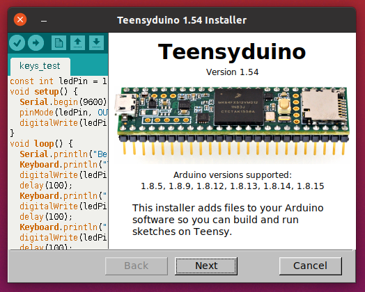
This article is a detailed look at the new & improved features version 1.54 brings.

MicroMod Teensy Support

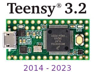
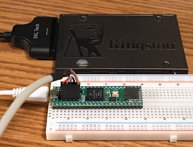
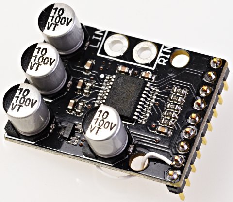
Sparkfun recently released MicroMod Teensy, which is a product of collaboration between PJRC and Sparkfun.

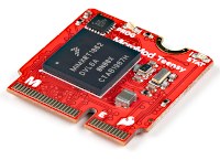
MicroMod Teensy has hardware similar to Teensy 4.0 (600 MHz ARM Cortex-M7, 1MB RAM), but with larger 16MB flash memory.

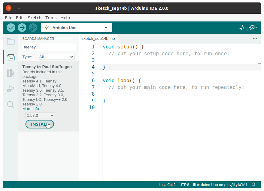
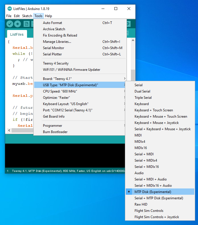
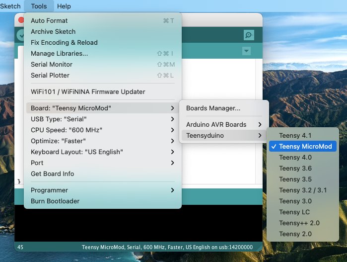
Teensyduino 1.54 brings full support for MicroMod Teensy.  Simply select it from Arduino’s Tools > Boards menu.

Teensy has traditionally focused on DIY electronics experimentation & building, particularly with solderless breadboards.  While a few shields exist, like the Audio board, PJRC doesn’t have the resources to create a large ecosystem of shields & accessories.  Almost all projects involve DIY building.

Sparkfun’s MicroMod form factor aims to give you an ecosystem of “just plug parts together” carrier boards and Qwiic I2C modules for a wide variety of projects.  If any of Sparkfun’s growing collection of carrier boards is a close fit to your project’s needs, and you’d rather buy something than experience the joy and learning (but also frustration) of DIY building, MicroMod carrier boards may save you a lot of time.

MicroMod can also be useful for low volume production.  Obviously at high volume you would create a fully custom design from the ground up, and at medium volume a custom PCB using the Teensy 4 bootloader chip can make good sense.  But for low volume production, keeping up-front costs low and minimizing money tied up in inventory is often the best path to success.  In those cases, you would manufacture a simple 2-layer PCB with as few expensive parts as possible, then populate it with Teensy and other complex modules at the time you actually sell.

Traditional Teensy requires through-hole header pins, which are simple but labor intensive to solder.  MicroMod form factor allows you to build your PCB using an inexpensive M.2 socket.  Then when you’re ready to sell a product, just buy the MicroMod board and plug it in.

Like all Teensy models, MicroMod Teensy is supported by Teensy Loader.

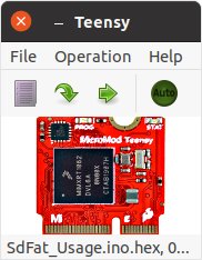
Teensy Loader is a stand alone program which can be used without the rest of Teensyduino and the Arduino IDE.  When you need to program a large number of boards with the same firmware, load the HEX file and turn on Teensy Loader’s “Auto” mode.  Then plug each board into a USB cable and press its Program / Boot button, or momentarily touch pads together if your custom PCB is made without a pushbutton.  Auto mode immediately uploads your firmware without requiring any keystrokes or mouse clicks!


Arduino 1.8.15 Support

Arduino released Arduino IDE 1.8.15 on May 15, 2021, and also version 1.8.14 several days earlier.

Teensyduino 1.54 brings full support for these 2 latest (non-beta) versions of the Arduino software.

If you are unsure which version you have, click Help > About to check.  On Macintosh, the About menu item is found under the program name rather than Help.


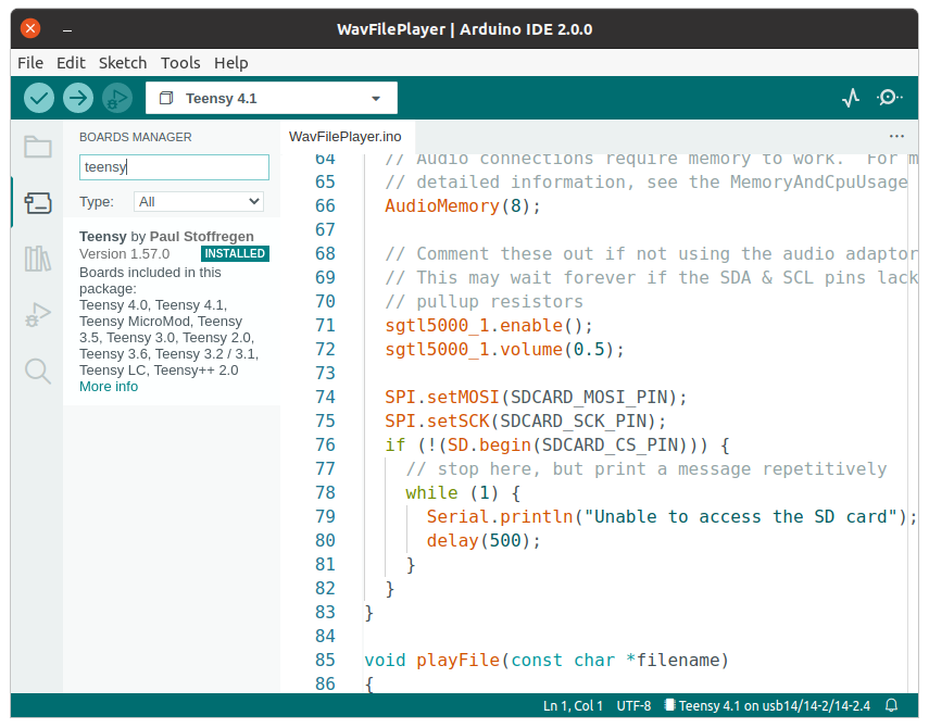
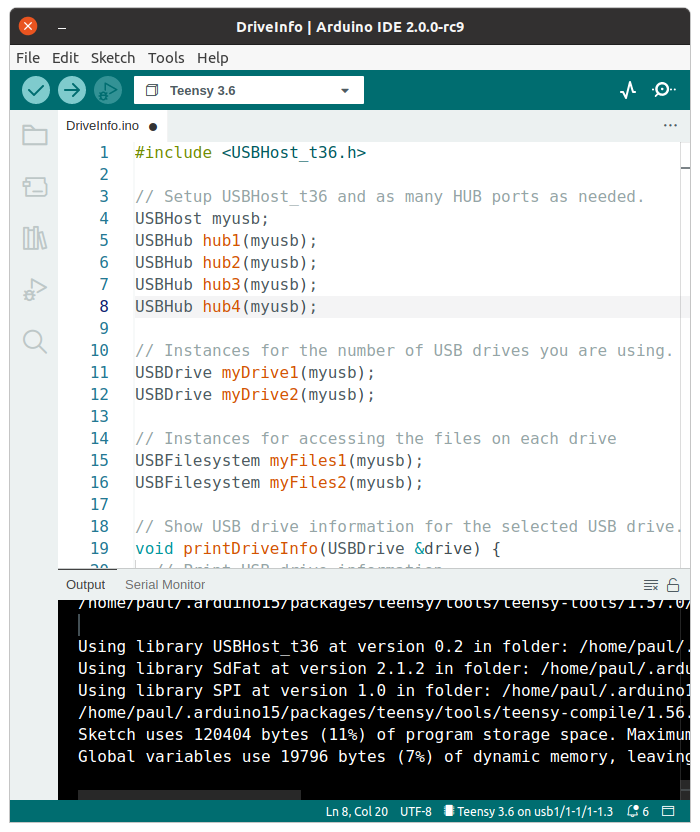
SD Cards Using SdFat with SD Library Compatibility

Until now, 2 different libraries were used to access SD cards.  The old Arduino SD library is used by most programs.  Bill Greiman’s SdFat library offers higher performance, support for large cards, and use of long filename rather than limited to 8.3 DOS filename format.

Teensyduino 1.54 has completely removed the very old Arduino SD library, which internally included an ancient version of SdFat.

SD.h has been replaced by a thin compatibility layer to allow all programs written to use the old SD library to still compile and function properly, but all SD card access is now actually performed with the SdFat library.

You can even mix usage of the traditional SD library and SdFat’s more capable API in the same program.  To do this, use “SD.sdfs” to access the SdFat instance within the SD compatibility layer.

One of the most useful ways to mix APIs is calling SdFat’s begin(), with SD.sdfs.begin() rather than the simple SD.begin() which offers only a choice of which pin to use for CS.  SdFat’s begin() lets you configure several hardware access optimizations.

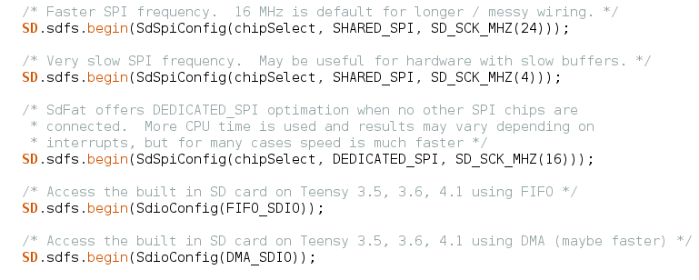
After using any of these, the SD card can be accessed using either SD library functions, or SdFat functions, or a mix of both.  For more detail, open File > Examples > SD > SdFat_Usage.


LittleFS for Files on Flash Chips

A LittleFS library is now included, providing littlefs published by ARM with a set of drivers for common memory chips and a high-level API compatible with the Arduino SD library.

Before 1.54, only the SerialFlash library was used for flash memory chips on Teensy.  SerialFlash provides essentially raw access to the underlying flash memory, which gives best performance, but comes with many limitations.  In particular, files must be created with a fixed size and can not grow in size beyond their original allocation.

LittleFS provides a traditional filesystem.  Files may be written as you would with the Arduino SD library.  LittleFS has flash memory wear leveling and copy-on-write behavior to protect against filesystem corruption if power is lost while writing, so LittleFS is a good choice for data logging or other applications which regularly write.  However, the copy-on-write behavior does impose overhead, making LittleFS slower than SerialFlash.

LittleFS supports flash memory chips on both the QSPI memory area of Teensy 4.1 and connected to the SPI ports.  FRAM memory chips are only supported on SPI ports.  Teensy’s built in memory can also be used.

These are the supported memory types with LittleFS in Teensyduino 1.54.

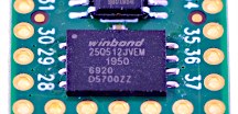
  • Winbond W25Q16JV*IQ / W25Q16FV
  • Winbond W25Q32JV*IQ / W25Q32FV
  • Winbond W25Q64JV*IQ / W25Q64FV
  • Winbond W25Q128JV*IQ / W25Q128FV
  • Winbond W25Q256JV*IQ
  • Winbond W25Q512JV*IQ
  • Winbond W25Q64JV*IM (DTR)
  • Winbond W25Q128JV*IM (DTR)
  • Winbond W25Q256JV*IM (DTR)
  • Winbond W25Q512JV*IM (DTR)
  • Adesto/Atmel AT25SF041
  • Spansion S25FL208K
  • Winbond W25N01G
  • Winbond W25N02G
  • Winbond W25M02
  • Cypress CY15B108QN-40SXI
  • Cypress FM25V10-G
  • Cypress FM25V10-G rev1
  • Cypress CY15B104Q-SXI
  • ROHM MR45V100A
  • Teensy 4.0, 4.1, MicroMod Program Flash
  • RAM Disk, internal RAM or PSRAM on Teensy 4.1

Use of program memory comes with some caveats.  While writing, your program may briefly stall when the flash memory is busy with an erase or write operation.  Uploading new programs fully erases the flash memory, destroying any saved files.  Future Teensyduino may provide a way to preserve the files across code uploading, but in 1.54 all files are lost.  Of course, this applies only to program flash.  Uploading code doesn’t alter data stored in other flash memory connected to the SPI ports or QSPI memory expansion.

To get started using LittleFS, check out the examples in File > Examples > LittleFS.  Documentation and more example code can be found in the LittleFS README file.


Audio Bandwidth Limited Waveforms

Audio waveform synthesis now supports bandwidth limited sawtooth, square, triangle and pulse waveforms, thanks to a contribution from Mark T.

These are the waveform types now supported by the waveform synthesis object.

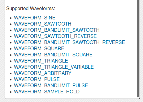
Bandwidth limited waveforms are useful when another waveform rapidly modulates frequency, phase or amplitude.  Modulation creates additional spectral content.  With standard full bandwidth waveforms, this new sound content can suffer from Nyquist aliasing.  Using bandwidth limited waveforms can avoid those aliasing problems.

Some people also feel the bandwidth limited waveforms simply sound better, or “more musical”.

Now you can have either standard or bandwidth limited waveforms, simply by changing the waveform name.  However, the bandwidth limited versions do require more CPU time.  Teensy 4.0, 4.1 or MicroMod are best for polyphonic synthesis where many bandwidth limited waveforms may need to be synthesized simultaneously.


Audio Ladder Filter

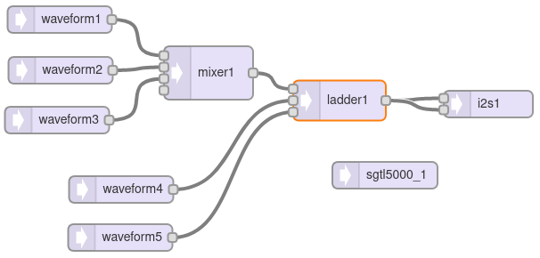
The audio library now includes a low-pass ladder filter, thanks to a contribution by Richard van Hoesel, based on the Oscillator and Filter Algorithms for Virtual Analog Synthesis paper published by Vesa Välimäki and Antti Huovilainen in Computer Music Journal 2006.30.2.19.

This ladder filter attempts to provide classic Moog sound when used with subtractive synthesis, where complex waveforms are generated with rich sound spectrum and then filtered, often using other waveforms to dynamically alter the filter’s parameters.

The ladder filter has 3 inputs, for the signal to filter, a control signal which can modulate the filter’s corner frequency, and another control signal which can modulate the filter’s resonance.

Like the original analog Moog filter, resonance can be adjusted or modulated all the way to cause self oscillation.  Many classic synthesizer sounds make use of this self oscillation feature.

Internally, this ladder filter uses hyperbolic tangent approximation and 4X oversampling to simulate the non-linear behavior of the original analog Moog filters.  An inputDrive() function is available to adjust the response from a very “clean” sound to the “dirty” overdrive mode popular with the Minimoog Model D synthesizer.

To quickly hear the ladder filter, open File > Examples > Audio > Synthesis > LadderFilter.

The ladder filter is numerically intensive.  While it technically can run on Teensy 3.5 & 3.6, for practical usage Teensy 4.0 should be considered the minimum required hardware.
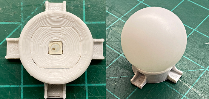
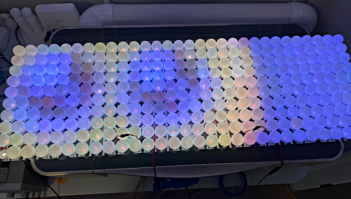
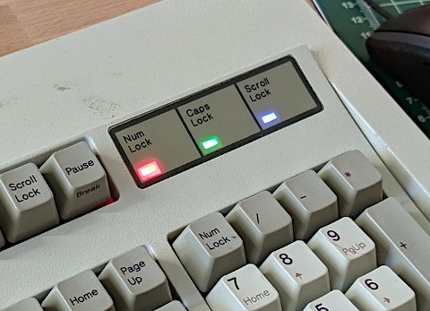
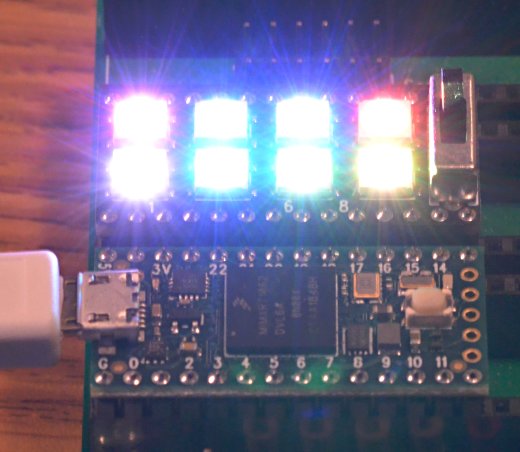
 

RGBW LEDs

Both WS2812Serial and OctoWS2811 now fully support WS2812,  WS2812B, SK6812 or “NeoPixel” RGBW addressable LEDs.  The additional white LED allows creation of pastel-like colors, and reliable white at greatly reduced power consumption.

These libraries use Direct Memory Access (DMA) to avoid blocking your program from running while the LED data is transmitted at 800 kbit/sec.  The non-blocking behavior gives your program more time to compute complex animations between LED updates.  It also prevents interference with audio, serial communication, or other libraries requiring interrupts.

On Teensy 4.0, 4.1, and MicroMod, OctoWS2811 can use any combination of digital pins, even while using RGBW LEDs, rather than only a fixed set of 8 pins as with older Teensy models.  For details, open File > Examples > OctoWS2811 > Teensy4_PinList.  Both libraries now include examples for RGBW.  If switching from RGB to RGBW, be sure to copy or update the buffer memory definition, as 4 bytes are needed for each LED rather than only 3.


FlexIO_t4 Library

FlexIO provides a sort of construction kit for building custom communication peripherals, using 32 bit shift registers, 8 & 16 bit timers, special control logic, and configurable signal routing to I/O pins.

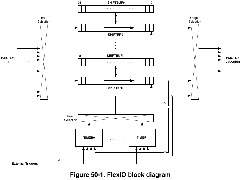
Each FlexIO port provides 8 shift registers and 8 timers.  The IMXRT1062 chip on Teensy 4.0 has 3 of these FlexIO ports.

Teensyduino 1.54 now includes the FlexIO_t4 library written by Kurt E.

First, this library provides objects for FlexSerial and FlexIOSPI classes, so you can create even more SPI and Serial ports, beyond the regular 8 serial ports and 3 SPI ports!

Second, the library provides dynamic resource management for the shifter & timer resources within each FlexIO port.  The goal is for libraries using FlexIO, such as TMM-HM01B0-Camera and TriantaduoWS2811, and FlexSerial & FlexIOSPI, to coordinate their usage of the shifter & timer resources.  While this resource coordination is still a work-in-progress, ideally in future versions you use any combination of these and other FlexIO libraries, they will automatically resolve which library instances utilize each shifter & timer within FlexIO ports.


Additional Serial Buffer Memory

Each hardware serial object, Serial1 to Serial8, has buffers for storing data recently received or ready to transmit.  For certain applications, you might like to increase the size of these buffers.

For example, if your loop() function performs tasks which need to happen regularly for proper functioning of your project, but also needs to occasionally transmit a large message on a serial port, the fixed buffer size can become an issue.

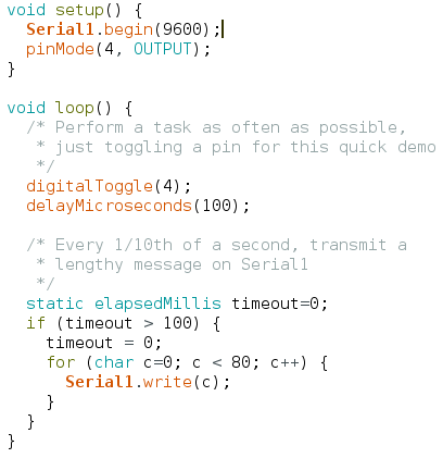
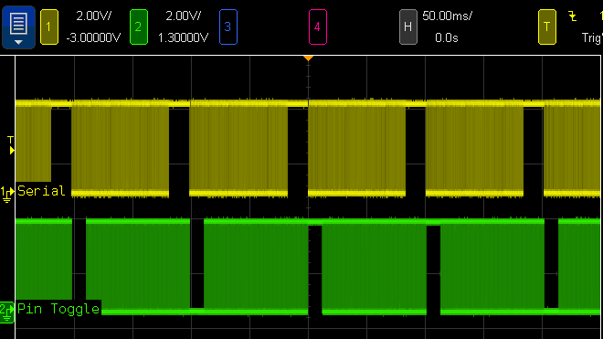
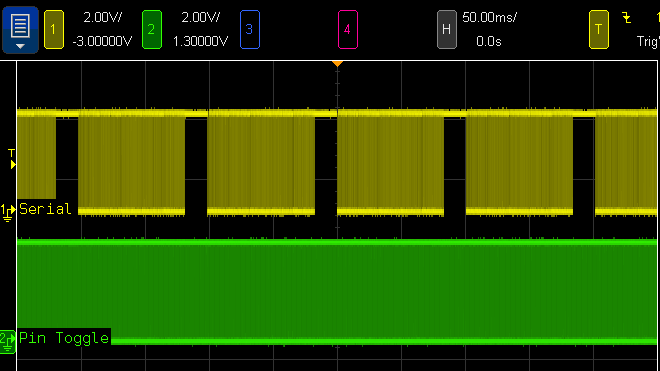
When this simple program is run, indeed the messages appear on the serial TX1 pin (yellow trace below) every 100ms.  But at the beginning of each message, pin 4 (the green trace below) stops changing for several milliseconds because Serial1.write() must wait for space in the transmit buffer.

The usual but complex solution to this problem is Serail1.availableForWrite(), which tells you how many bytes can be written without incurring extra delay.  However, this requires restructuring your program to write the outgoing message in multiple pieces.  If the message contains data which may change over time, perhaps you make a copy of all the data.  Doable, but complicated.  Everything would be so much simpler if you could increase the Serial1 buffer size.

Now you can increase the serial buffer sizes on all 32 bit Teensy boards, thanks to contributions from Kurt E.  To increase the Serial1 transmit buffer, you use Serial1.addMemoryForWrite().

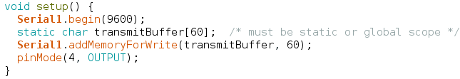
You create an array of bytes to serve as the extra memory.  The array MUST be either static or global scope, because Serial1 will continue using it long after the current function ends.

When this program is run with extra buffer memory, the green trace never stops.  The loop() function never stalls waiting on Serial1.write() because the buffer is now large enough to hold the entire outgoing message.

Of course, you can also increase the receive buffer with Serial1.addMemoryForRead().  If your program spends time doing lengthy computations or other work while serial data is arriving at a high baud rate, extra buffer memory can help avoid the loss of incoming bytes.


More Serial RX & CTS Pin Choices

Teensyduino 1.54 also brings more choices for which pins to use to receive serial data and flow control signals, on Teensy 4.0, 4.1, and MicroMod.  Thanks to another contribution from Kurt E, you can now use pins 0, 1, 2, 3, 4, 5, 7, 8, 30, 31, 32, 33 with any of the Serial1 to Serial8 setRX(pin) and attachCts(pin) functions.

Normally the serial signals connect to the pins through a multiplexer which allows 1 of 8-10 peripherals to control the pin.  This new feature automatically routes the serial receive and CTS receive signals through the “XBAR” (crossbar trigger network) peripheral to open up many more choices than could be configured using only the normal pin multiplexers.

This is particularly valuable for use of hardware RTS / CTS flow control, which allows fast baud rates up to 6 Mbit/sec to be used reliably with “normal” programs which may not always read incoming data rapidly.  Serial1 to Serial8 support transmitting RTS on any pin, but with prior software, only Serial3 and Serial5 on Teensy 4.x could receive CTS (and Serial5 only supported CTS on a SD card pin).  Now RTS / CTS flow control can be used easily with any of the 8 serial ports.

One caveat, however, is each serial port may only route one input signal through the XBAR peripheral.  For each serial port, you may use either setRX() or attachCts() with these special XBAR pins, but not both.


Improved map()

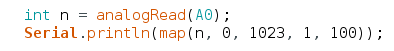
Arduino’s map() function provides a convenient way to scale a number from one range to another.  One common use is scaling the analog input pins, which give 0 to 1023 with default settings, to another range, such as 1 to 100.

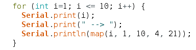
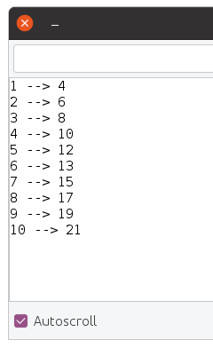
Traditionally, map() has worked only with integer numbers.  For example, mapping 1-10 to 4-21:

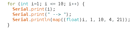
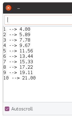
Sometimes you may want more precision.  With Teensyduino 1.54, map() now automatically uses floating point math, if the input variable is float or double type.  You can store your number into a float variable, or convert it to float right at the map input.

Of course, if you want the traditional integer-based map(), simply use an integer type for the input.  Internally, a little C++ template magic is used to automatically use the integer version when your input is an integer type, or the float version when your input is float or double.  If using 64 double, the math is done with full 64 bit precision.

Arduino map() has a long history of suffering integer round-off errors.  For most applications, these errors are small and never noticed.  But they are errors nonetheless.

Teensyduino 1.54 fixes the integer map() equation, so the integer results agree with the precise floating point results, when the float numbers are properly rounded to the nearest integer.


delayNanoseconds() on all Teensy Models

All Teensy models now have a delayNanoseconds() function, even on Teensy 2.0.  When you need a very short delay, this function is simple and easy to use.

Often the actual delay will often be slightly longer than requested.  Just like delayMicroseconds() and delay() for milliseconds, it will always delay for at least the time specified.

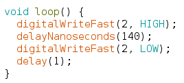
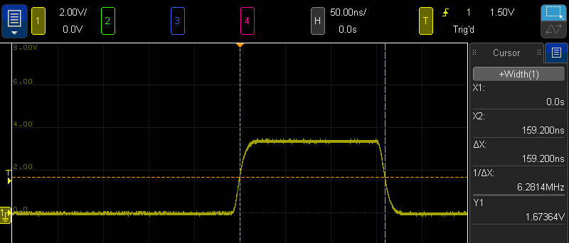
In this simple example, a 140ns delay is used between changing a pin.  The actual resulting pulse measures 159ns.

Internally, delayNanoseconds() is implemented differently on Teensy 2 & 3 than on Teensy 4.  The older boards use a simple busy loop with “nop” instructions.  This gives the best performance on those older & simpler architectures.  But if an interrupt occurs during the delay time, the delay continues after the interrupt without any awareness its total time was lengthened.

Teensy 4 has a very different delayNanoseconds() implementation.  Because Cortex-M7 relies on caching both data and instructions, and uses multiple types of memory with very different latency for cache misses, busy looping is not as predictable as with the older architectures.  Instead, the desired nanoseconds are converted to CPU cycles, and the a wait loop polls the ARM DWT cycle counter.  While this adds overhead before the delay begins, the result is highly predictable results regardless of memory & cache.  An added benefit is resilience to interrupts which may occur during the delay.

Normally delayNanoseconds() is used with a constant input for the nanosecond time.  Inline code is used, where the compiler is able to better optimize results when the input is a constant.  However, variables not known as constants at compile time may be used.  All 32 bit boards still give fairly good results.  On Teensy 2.0, use of variable input results in delay precision of about 1 microsecond.


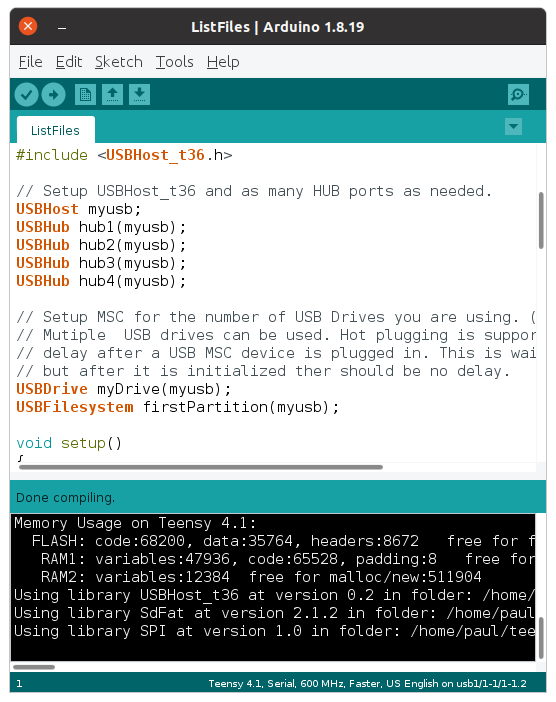
Detailed Memory Usage Report

Prior Teensyduino versions used Arduino’s default memory usage summary after compiling.

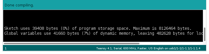
For Teensy 4, this simple memory report leaves much to be desired.

Teensy 4.0 & MicroMod have 3 distinct memories.  Teensy 4.1 has 4 distinct memory areas, if PSRAM chip(s) have been added.

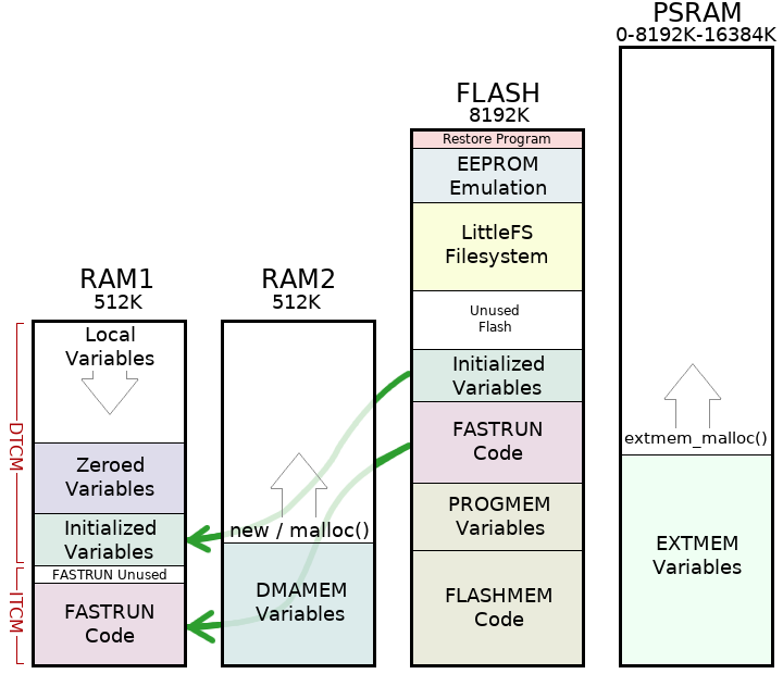
Arduino’s simple memory usage also assumes RAM is only used for variables and flash is only used for code.  On Teensy 4 boards, the RAM1 memory is partially used for code.  Because the hardware supports partitioning RAM between Instruction Tightly Couple Memory (ITCM) and Data TCM in 32K blocks, a portion of the last 32K block of ITCM is unused padding.

Teensyduino 1.54 brings a more detailed memory usage summary which shows how each of the 3 or 4 memory regions are actually used.

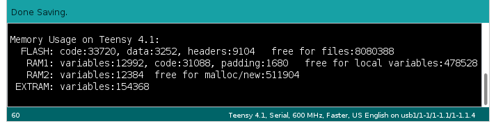
Flash memory usage is given in more detail.  One common issue is large arrays of constant data, such as lookup tables to speed computations or digital media like sound clips & fonts, can be mistakenly allocated to RAM.  The report now shows how much is data versus code, so you can easily see the change in data stored in flash while working with such const data arrays.

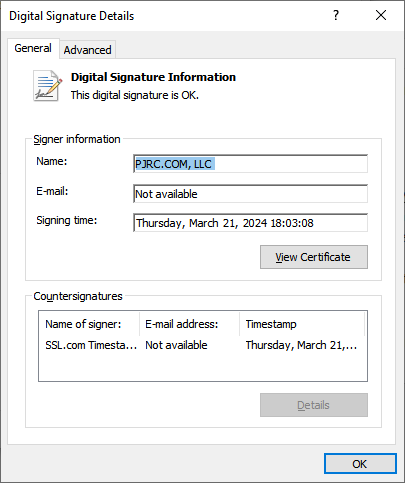
A portion of flash memory usage is reported as “headers”.  Slightly over 4K at the beginning of flash memory is reserved for data used by the IMXRT startup process.  3K at the end of your program is reserved for a digital signature.  Up to 2K of padding may be used to align these areas to 1K boundaries.  By reporting these as “headers”, they’re not mixed in with the code and data your program uses, giving you a more accurate view of how your program is really using the flash memory.


Fault Recovery & CrashReport

Teensy 4.0, 4.1 & MicroMod have a Memory Protection Unit (MPU) built into the ARM Cortex-M7 processor.  The MPU allows permissions and caching configuration to be established on up to 16 memory regions.  This is much simpler than a Memory Management Unit (MMU) found in PCs, which translates addresses to implement virtual memory.  The MPU only enforces permissions, such as whether reading, writing or code execution is allowed in each memory region.

Since the earliest Teensy 4.0 beta tests, the MPU has been configured with security conscious settings, such as only allowing code to execute from flash and ITCM memory regions and disallowing any access from a NULL pointer.  But if your program “crashed” by violating any MPU permissions or otherwise caused a fault exception, the default fault handler was essentially empty.  Teensy 4.0 & 4.1 would stop responding and a press of the pushbutton was needed to recover.

Teensyduino 1.54 includes an improved default fault handler to recover from problems and give you information to help diagnose what went wrong.  The new fault handler performs these actions.

  1. Log processor state & other useful info to RAM
  2. Reduce CPU speed to 198 MHz
  3. Complete USB transmission, so all Serial.print() data buffered before the fault (hopefully) arrives at the Arduino Serial Monitor
  4. Try to remain USB responsive to Arduino’s Upload button
  5. Automatically reboot after 8 seconds

Because this fault handler is built into all programs, and because it runs when something has gone very wrong, its code is meant to be kept simple & small.  Diagnostic info is written to a fixed location in RAM (which is preserved when restarting), rather than communicated at the time of the fault.

The automatic reboot may controversial.  Rebooting tends to hide the fact a problem occurred.  For most applications where Teensy always runs an application specific program, automatically restarting to recover from a problem is probably better than remaining forever unresponsive.

The 8 second delay was chosen for 2 reasons.  Traditionally watchdog timers are used for automatic rebooting.  If any of the 3 watchdogs are in use, they can function normally if configured for less than 8 seconds.  The 8 second delay is also meant to prevent a rapid infinite rebooting loop in the case where the program quickly causes another fault.  Hopefully 8 seconds is a good balance between promptly recovering, avoiding difficult to understand reboot-loop behavior, and allowing normal watchdog usage.

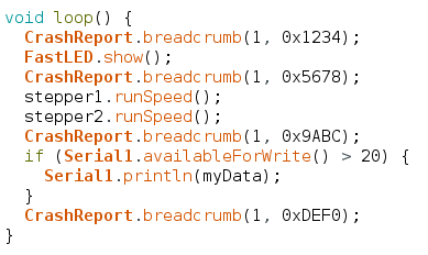
After Teensy reboots, your program can access the logged information with CrashReport.  The CrashReport code is only built into your program if you actually use it.  While your program can use CrashReport at any time, it is meant to be used early in your program’s startup, hopefully before anything has gone wrong, so you have fully access to a freshly rebooted system.

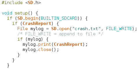
The simplest CrashReport usage is with a single Serial.print() line.

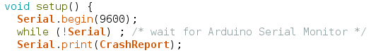
If your program previously crashed with a fault or unused interrupt which logged information, CrashReport shows you a summary.

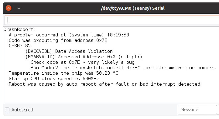
CrashReport can be tested as true/false, to tell you whether information was logged.  You might use this with a program that rapidly prints to the serial monitor, to show the info and wait for input before continuing on to run the program which quickly scrolls the CrashReport info off your screen.

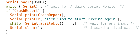
CrashReport is not limited to use with only the Arduino Serial Monitor.  It can be used with any interface inheriting the Arduino Print class.  For example, you can store CrashReport to a file on a SD card or a flash chip with LittleFS, to keep a record of every time a fault was detected.

The default fault handler and CrashReport can not handle every possible error.  The MyFault library was created as a collection of test cases for fault recovery and CrashReport, and also has a typical usage example.

Bug Fixes and Minor Improvements

Teensyduino 1.54 also includes many bug fixes, minor features & improvements, and updated libraries.  A detailed list of all changes can be found on this forum announcement thread.

PCM1802 Breakout Board Needs Small Hack

PCM1802 is an impressive audio A/D converter, specified for 105 dB signal to noise (A weighted).  But people have reported problems using very cheap PCM1802 breakout boards.  Today I made it work.

The cheap PCM1802 boards are sold my many Chinese companies, usually for just a few dollars.

Update: since this article was written, new PCM1802 breakout boards have appeared on the market which may have another design problem with the configuration pins.  PJRC has not yet tested any new PCM1802 with this issue.

The PCM1802 tested in this article came from this AliExpress vendor.

The main issue with these PCM1802 boards involves configuring the data format.  Teensy and most microcontrollers use I2S format.  The board comes with no documentation, but the PCM1802 datasheet shows how to configure the chip in table 6.

On the bottom side of the PCM1802 breakout are little solder pads with names that match up with the datasheet.

If you power the board, the FMT0 and FMT1 pads measure 0 volts.  Without power, the also measure about 9K ohms to GND.

To configure for I2S, you would expect to just solder the 2 pads next to FTM0 together.  But there is a problem…

These 5 pads labeled “+” connect to each other, but they do NOT connect to 3.3V or anything else on the circuit board!  Soldering the FTM0 pads together has no effect.

To make this work, I soldered a wire to those pads.

There is no location on the bottom of the board to access 3.3V power.  I considered using the OSR pad.  But the pullup resistor is only 10K.  The PCM1802 has 50K pulldown resistors, according to the datasheet.  Indeed with power applied, I measured 2.8 volts at the OSR pad.

So to get 3.3V, I ran the wire to the top side and soldered it to the 3.3V pin.

The SOT23 part in the lower left corner of this photo is a 3.3V regulator.  This 3.3V pin is an output, not an input, which I also verified with my voltmeter.

Fortunately, all of the other pins in this PCM1802 board are wired correctly for use with Teensy’s I2S.  In its default mode, only DOUT is an output.  All of the other signals are inputs.

These are the required connections between Teensy 3.6 and the PCM1802 breakout board.

PCM1802 Teensy 3.6
   +5V               VIN
   3.3V
   GND              GND
   DOUT            DIN (13)
   BCK               BCLK (9)
   FSY               3.3V
   LRCK             LRCLK (23)
   POW              3.3V
   SCK               MCLK (11)

The POW pin is the only name which doesn’t match up with the PCM1802 datasheet.  I used my ohmmeter to verify it really is connected to the PDWM pin.

The FSY pin (connected to FSYNC) is also a bit unusual.  PCM1802 expects it to be logic high while you transmit data, so just connect to 3.3V.  In the other modes, it sends a signal on this pin which is high during data bits and low during the zero padding bits.  But it does not require that signal as input.  FSYNC just connects to 3.3V to use PCM1802 with Teensy.

For a simple test, I programmed Teensy 3.6 with minimal code to just route the I2S input data to the two DAC pins.

#include <Audio.h>

AudioInputI2S i2s1; //xy=152,100
AudioOutputAnalogStereo dacs1; //xy=316,117
AudioConnection patchCord1(i2s1, 0, dacs1, 0);
AudioConnection patchCord2(i2s1, 1, dacs1, 1);

void setup() {
 AudioMemory(10);
}

void loop() {
}

With FMT0 correctly configured using a mod wire, and those connections, PCM1802 works great with Teensy.  Here are closer photos of the wiring.


If you need a high quality audio A/D and you can find these cheap PCM1802 breakout boards, hopefully this tip about the FTM0 hack and known-good wiring can save you from some frustration and get your project up and running quickly.