|
|
Using an IDE Hard Drive with a 8051 Board and 82C55 Chip
This page describes a simple design that connects a standard IDE interface
hard drive to a 8051 board, such as the
newer development board,
using the 82C55 chip. Figure 1 shows the board and drive
that was used to test this code.
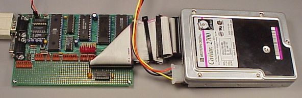 |
| Figure 1: Development Board With IDE Drive Connected |
This
code only provides the ability to access raw sectors. It does not
implement a filesystem, such as FAT16 or FAT32 or even Linux romfs.
If you want to
access data stored by DOS/Windows, or store data that will be readable
without special drivers... well, you'll have a lot of code to write!
If your project is well funded, you could buy the filesystem code from a
company such
as US Software (now defunct).
Update: the New MP3 Player project has
firmware with FAT32 support.
The speed is slow. Data transfer is not fast,
compared with a PC computer. The 8051 isn't fast, and there is
overhead dealing with the 82C55 chip. There is a somewhat faster
(optimized) version
of this code available, but without much information about the
optimizations. The faster
version was used in a project that sustained reads of 24 kbytes/sec,
while also doing some serial communication, with a 14.7456 MHz
system clock. The normal version is
believed to be able to read at about 16 kbytes/sec, but this hasn't
been verified.
These routines wait for the drive to complete its operations using
busy loops. There are no timeouts, so if the drive fails or becomes
disconnected, the code may hang forever waiting for the drive. For
any sort of serious application, at least timeouts should be added,
and some applications must not have busy loops, so this code
would need to be restructured somewhat. Still, it is a working
example that should provide a reasonable start for a 8051-based
project that needs to access a hard disk drive.
And of course, there is no warranty of any kind (see the
download section), but it's free.
Peter Faasse, some time ago
wrote a very nice text file about interfacing an IDE hard drive
to a 63B03 using a 8255 chip. Copies may be found at
Wesley's PIC Pages
(nice HTML version),
or this
zip file containing the original text file.
Peter's paper was very helpful and was the primary source I used to
learn about the IDE interface. Peter's paper gives a very
good example to follow and it explains the IDE interface very nicely.
Peter's project interfaced an IDE drive with an 8255 chip, which
luckily was the same one I wanted to use. I would not have initially
used the inverters, without his warning about the 8255's funny
behaviour when it is reconfigured.
Alex T. Ivopol's
IDE - Hardware Reference in a
good technical summary of IDE/ATA. This is where I first learned
about the 0x91 command (see the LBA section).
Peter den Haan's
Enhanced IDE FAQ
is also a great place to look for information, though it's more oriented
towards PC users than embedded systems developers. Peter has links to
most of the on-line resources.
The ATA specs appear to no longer be available on-line, and need
to be ordered $$$ from ANSI. I did not order any of them, so bear
in mind that some of this material was based on a bit of guesswork,
and the prior work of Peter Faasse did. Update: it looks
like you can get copies on-line now, the
docs page at Peter
Kovacs's mp3projects.com site seems to have a good set of links.
Other home-built MP3 player project pages also have copies or links
now.
After doing this project, I found other similar pages. The one at
Zel Electronics
claims to interface to an 8255 chip. They give
details about the hardware, but they don't show a copy of their code.
Carsten Groen
has a page that gives C code, but not much info about the hardware
required.
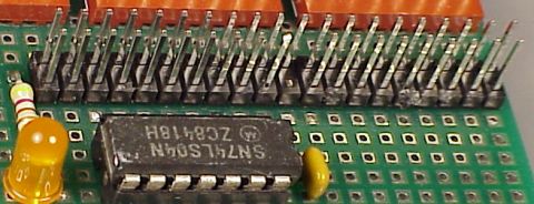
It's remarkably easy to connect an IDE drive to the 8255. Figure 2 shows the
the construction used to add the IDE interface to a development board. It
is important to keep in mind where pin 1 is located. Many of the diagrams
available on the net, including Peter's text file, show the pinout for the
IDC (ribbon cable mount) socket, looking into the holes. If you build this
circuit, it's a good idea to refer to these figures or a known-correct board
with the pins clearly labeled.
|
| Figure 2: IDE Interface Circuit. Very few parts
are needed. Pin 1 is located at the upper right. Pin 20 is removed. Had a
connecter with a polarizing notch been used, the notch would appear at the top
of this picture, opposite the even numbered side, with pin 20 removed. |
A 74HC04
(or similar inverter chip), the IDE connector, and wires are about
all you will need. The LED shows drive activity, just like one on the
front of a PC. I used the inverter because of Peter's suggestion of
the troubles with the 8255. I did not try without the inverter and
inverting the signals in the code. Figure 3 shows the schematic
between the 82C55 chip and the IDE connector. For the board itself,
see the
development board schematic page.
| | Figure 3: Schematic Diagram, only one chip and a few
passive parts are required to connect the IDE drive to the 82C55 chip.
|
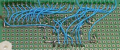
Making the connections with point-to-point wiring is relatively easy.
Figure 4 shows the wiring I used. Pay careful attention to which port
is which and where pin 1 is located. It can be easy to get it backwards...
or at least it was easy for me on my first attempt.
|
| Figure 4: Point to Point Wiring, to connect the
components as shown above. Note the dot on the left side of the IDE connector,
which marks pin 1. Along the top, Port A is on the left, Port B is in the middle,
and Port C is on the right.
|
Originally I tried to access the hard drive using Cylinder/Head/Sector (CHS)
addressing, and it would not work properly. All of these early attempts
were with a Western Digital 1.2 gig drive. I could read the first sector, C=0, S=0, H=0, also known as the Master Boot Record (MBR), but reading
from other parts of the drive would not work.
After much frustration, I discovered that the drive wanted to receive
the Initialize Drive Parameters (0x91) command. I didn't find much
documentation about this command on-line. I deleted all the code I wrote
for CHS (except for printing info from the drive ID command).
Logical Block Addressing (LBA) is much simpler and easier to use than CHS,
and it's supported by all modern drives. With LBA, the entire drive
appears as one giant array of 512 byte sectors. To access any sector,
you just use one 28 bit unsigned integer to specify which one you want.
The numbering is zero based, so to read the MBR, you specify 0. The
code uses a 32 bit parameter, with the upper 4 bits ignored.
The PC computer world has known a number of barriers regarding
hard drive size, at 32M, 528M, 2G, and 8G. These limits have been
due to the filesystems used by DOS/Windows, and the parameter passing
between the BIOS and DOS/Windows, and how the bits were allocated in
those parameters, between Cylinders, Heads and Sectors. This code
passes a single 32 bit (LBA)
number, instead of 24 bits (CHS) used in the legacy PC bios calls.
If you're quick with binary numbers (I am not past 65536), you probably
already know that 28 bits allows 268435456 512 byte sectors, which is
128 gigabytes in computer speak, or 137 gig for hard drive marketing
speak.
I wonder what they'll do when the LBA address space runs out. With
IBM's new 75 gig drive, it won't be long...
The example program contains four sections. The first part (not
described much here) implements a small one-line menu program that
lets you easily excersize the various functions from Paulmon2,
without having to write any code. The IDE interface code is in
two sections, one that is intended to be used by a program, and a
group of low level routines. The last portion of the code are
a few misc serial I/O routines not available in Paulmon2, such as
the 8-byte version of ghex, used for entering a 32 bit LBA address
at the menu.
IDE Access Routines
read_sector
- Read a 512 byte sector, specified by the 32 bit number in
the lba variable (internal memory). The 512 bytes are transfered
to extern memory specified by buffer. A status code is returned
in Acc. Acc is cleared to zero on success, or set to a non-zero value
if an error occurs. The error code returned is the error status code
from the IDE drive.
write_sector
- Write a sector to the drive, at the location specified by lba.
The 512 bytes from the buffer are written. A status code is returned
in Acc. Acc is cleared to zero on success, or set to a non-zero value
if an error occurs. The error code returned is the error status code
from the IDE drive.
drive_id
- Ask the drive to return info about itself. This work almost exactly
like the read_sector routine, except the drive's ID info is returned in
the 512 byte buffer instead of a sector. The example program prints
out a few of the fields from this data. For a list of which bytes
mean what, grab the Linux source code. On my linux machine (2.2.13),
the info is in this file: /usr/src/linux/include/linux/hdreg.h, expressed
as a "struct hd_driveid", beginning on line 147.
spindown
- Ask the drive to shut down. It will stop spinning. There is not
check to make sure the drive really does shut down.
spinup
- Ask the drive to power up. This routine will wait until the
drive says that it is ready to execute commands.
ide_init
- This routine should be called before attempting to use the drive.
It selects the master device, and waits for it to be ready. If this
is called shortly after applying power to the drive, it will end up
waiting until the drive spins up and finished its self check. This
routine sends the Init Parameters command. You may need to edit the
constants sent to the drive. It also sends the Recal command, which
may be totally unnecessary. There is no return value for success or
failure. If there is no drive connected, this code will probably
hang and never return.
Low-Level Routines
Ordinarily you wouldn't call these routines from your main
program. They are intended to be used by the above routines.
read_data
- Transfer 512 bytes from the drive to the 8051's buffer in
external memory.
wr_lba
- Copy the LBA number from the 4-byte lba variable in
internal ram to the drive's registers.
ide_busy
- Wait while the drive is busy. This will wait forever if
the drive stays busy for some reason. A timeout should probably
be added.
ide_drq
- Wait for the drive to be ready to transfer data. This will
wait forever if the drive never says it is ready. A timeout
should probably be added.
ide_rd
- Read from one of the drive's registers. Acc specifies which
register to read, and R2/R3 contain the 16 bit data. For 8 bit
reads, just ignore R3.
ide_wr
- Write to one of the drive's registers. Acc specifies which
register to write into, and R2/R3 contain the 16 bit data. For 8
bit writes, the drive ignores whatever is in R3.
ide_hard_reset
- Give the drive a physical reset signal.
This code always attempts to access the Master IDE device. It
will not work correctly if you connect one device, configured to
be a IDE Slave device. Many hard drives, including the Western
Digital drives I've used, can be configured as Master, Slave,
Stand Alone, and Cable Select. For the Western Digital drive,
the stand alone mode is with no jumpers installed, and the other
three correspond to placing a jumper in one of three positions.
The stand alone mode configures the drive as a Master, but it
differs from the Master setting in that it doesn't wait for the
Slave device when doing the self test after a hard reset. Other
than starting up much sooner, I could not find other differences
between the Master and stand alone setting.
Pin 34 (PDIAG) should not be connected. Without the ATA spec,
I can only make some guesses about this pin. It seems to be used
by the drives during their self-test. It is not used to select
which drive will execute a command.
There is no specific hardware pin that select which drive will
execute a command. The Master vs Slave selection is done by
setting or clearing a bit in the Head register. Both
drives hear the computer writing, but only the drive that heard
its setting will respond to the command. To use a Slave device,
this bit would need to be changed in ide_init and wr_lba.
The example code includes a small one-line menu program which
let's excersize the functions easily. The program is intended
to run with PAULMON2. Here is simple session using the program.
First, download the code to PAULMON2, just like any other normal program.
               Welcome to PAULMON2, by Paul Stoffregen

  See PAULMON2.DOC, PAULMON2.EQU and PAULMON2.HDR for more information.


Program Name                     Location      Type

PAULMON2 Loc:2000 > Download

Begin ascii transfer of Intel hex file, or ESC to abort

...........................................................................
Download completed

Summary:
 75  lines received
 1166  bytes received
 1166  bytes written
No errors detected
|
Just press R to run the program.
PAULMON2 Loc:2000 > Run program

  A - IDE Disk Drive Test
run which program(A-A), or ESC to quit: A

IDE Disk Drive Test Program

Model: 7200 H
S/N:   DWW-2T68303516 8
Cylinders: 1416, Heads: 16, Sectors: 63

LBA=0x00000000, (R)ead (W)rite (L)BA (U)p (D)own (H)exdump (Q)uit
|
When you first run the program, it will initialize the drive, which
should cause it to begin spinning. Most drives will spin up without
a computer attached, but with the drive connected, it should wait
until the program is run. Once the drive says it is ready, the
program asks the drive for its ID info, and prints a few of the
items. In this case, the drive is a Western Digital Caviar 2700.
The Cylinders, Heads and Sectors shown are only the values that the
drive reported. All of the code here uses
Logical Block Addressing. These CHS values aren't
used, but they should correspond to the ones printed on the drive's
label.
As a first step, let's read a sector. When the program starts up,
the default address is 00000000, the first sector on the drive,
which is the Master Boot Record that contains the partition table.
To read the sector, just press R to read, and H to
hexdump the buffer.
Sector Read OK
LBA=0x00000000, (R)ead (W)rite (L)BA (U)p (D)own (H)exdump (Q)uit

0000: FA 33 C0 8E D0 BC 00 7C 8B F4 50 07 50 1F FB FC    z3@ P< | tP P {|
0010: BF 00 06 B9 00 01 F2 A5 EA 1D 06 00 00 BE BE 07    ?  9  r%j    >>
0020: B3 04 80 3C 80 74 0E 80 3C 00 75 1C 83 C6 10 FE    3  < t  < u  F ~
0030: CB 75 EF CD 18 8B 14 8B 4C 02 8B EE 83 C6 10 FE    KuoM    L  n F ~
0040: CB 74 1A 80 3C 00 74 F4 BE 8B 06 AC 3C 00 74 0B    Kt  < tt>  ,< t
0050: 56 BB 07 00 B4 0E CD 10 5E EB F0 EB FE BF 05 00    V;  4 M ^kpk~?
0060: BB 00 7C B8 01 02 57 CD 13 5F 73 0C 33 C0 CD 13    ; |8  WM _s 3@M
0070: 4F 75 ED BE A3 06 EB D3 BE C2 06 BF FE 7D 81 3D    Oum># kS>B ?~} =
0080: 55 AA 75 C7 8B F5 EA 00 7C 00 00 49 6E 76 61 6C    U*uG uj |  Inval
0090: 69 64 20 70 61 72 74 69 74 69 6F 6E 20 74 61 62    id partition tab
00A0: 6C 65 00 45 72 72 6F 72 20 6C 6F 61 64 69 6E 67    le Error loading
00B0: 20 6F 70 65 72 61 74 69 6E 67 20 73 79 73 74 65     operating syste
00C0: 6D 00 4D 69 73 73 69 6E 67 20 6F 70 65 72 61 74    m Missing operat
00D0: 69 6E 67 20 73 79 73 74 65 6D 00 00 81 59 42 17    ing system   YB
00E0: 00 00 00 00 00 00 00 00 00 00 00 00 00 00 00 00
00F0: 00 00 00 00 00 00 00 00 00 00 00 00 00 00 00 00
0100: 00 00 00 00 00 00 00 00 00 00 00 00 00 00 00 00
0110: 00 00 00 00 00 00 00 00 00 00 00 00 00 00 00 00
0120: 00 00 00 00 00 00 00 00 00 00 00 00 00 00 00 00
0130: 00 00 00 00 00 00 00 00 00 00 00 00 00 00 00 00
0140: 00 00 00 00 00 00 00 00 00 00 00 00 00 00 00 00
0150: 00 00 00 00 00 00 00 00 00 00 00 00 00 00 00 00
0160: 00 00 00 00 00 00 00 00 00 00 00 00 00 00 00 00
0170: 00 00 00 00 00 00 00 00 00 00 00 00 00 00 00 00
0180: 00 00 00 00 00 00 00 00 00 00 00 00 00 00 00 00
0190: 00 00 00 00 00 00 00 00 00 00 00 00 00 00 00 00
01A0: 00 00 00 00 00 00 00 00 00 00 00 00 00 00 00 00
01B0: 00 00 00 00 00 00 00 00 00 00 00 00 00 00 00 01
01C0: 01 00 0B 1F BF C2 3F 00 00 00 61 BF 15 00 00 00        ?B?   a?
01D0: 00 00 00 00 00 00 00 00 00 00 00 00 00 00 00 00
01E0: 00 00 00 00 00 00 00 00 00 00 00 00 00 00 00 00
01F0: 00 00 00 00 00 00 00 00 00 00 00 00 00 00 55 AA                  U*
|
This is the MBR on this drive. The first 192 are the bootloader that is
run by the bios after it reads this sector.
The sixteen bytes shown in red
are the first entry of the partition table.
The last eight bytes indicate the where the partition begins, and how many
sectors it contains, both in LBA units. The 3F 00 00 00
indicates that the first sector is at address 0000003F. The partition
is 0015BF61 sectors long. That's 1425249 sectors, each 512 bytes long,
which is 695.92 megabytes of data.
Next, let's read the first sector of the partition, at LBA address 3F.
LBA=0x00000000, (R)ead (W)rite (L)BA (U)p (D)own (H)exdump (Q)uit
Enter LBA (in hex): 3F
LBA=0x0000003F, (R)ead (W)rite (L)BA (U)p (D)own (H)exdump (Q)uit
Sector Read OK
LBA=0x0000003F, (R)ead (W)rite (L)BA (U)p (D)own (H)exdump (Q)uit

0000: EB 58 90 4D 53 57 49 4E 34 2E 31 00 02 08 20 00    kX MSWIN4.1
0010: 02 00 00 00 00 F8 00 00 3F 00 20 00 3F 00 00 00         x  ?   ?
0020: 61 BF 15 00 6F 05 00 00 00 00 00 00 02 00 00 00    a?  o
0030: 01 00 06 00 00 00 00 00 00 00 00 00 00 00 00 00
0040: 80 00 29 FE 18 37 05 4E 4F 20 4E 41 4D 45 20 20      )~ 7 NO NAME
0050: 20 20 46 41 54 33 32 20 20 20 FA 33 C9 8E D1 BC      FAT32   z3I Q<
0060: F8 7B 8E C1 BD 78 00 C5 76 00 1E 56 16 55 BF 22    x{ A=x Ev  V U?"
0070: 05 89 7E 00 89 4E 02 B1 0B FC F3 A4 8E D9 BD 00      ~  N 1 |s$ Y=
0080: 7C C6 45 FE 0F 8B 46 18 88 45 F9 38 4E 40 7D 25    |FE~  F  Ey8N@}%
0090: 8B C1 99 BB 00 07 E8 97 00 72 1A 83 EB 3A 66 A1     A ;  h  r  k:f!
00A0: 1C 7C 66 3B 07 8A 57 FC 75 06 80 CA 02 88 56 02     |f;  W|u  J  V
00B0: 80 C3 10 73 ED BF 02 00 83 7E 16 00 75 45 8B 46     C sm?   ~  uE F
00C0: 1C 8B 56 1E B9 03 00 49 40 75 01 42 BB 00 7E E8      V 9  I@u B; ~h
00D0: 5F 00 73 26 B0 F8 4F 74 1D 8B 46 32 33 D2 B9 03    _ s&0xOt  F23R9
00E0: 00 3B C8 77 1E 8B 76 0E 3B CE 73 17 2B F1 03 46     ;Hw  v ;Ns +q F
00F0: 1C 13 56 1E EB D1 73 0B EB 27 83 7E 2A 00 77 03      V kQs k' ~* w
0100: E9 FD 02 BE 7E 7D AC 98 03 F0 AC 84 C0 74 17 3C    i} >~},  p, @t <
0110: FF 74 09 B4 0E BB 07 00 CD 10 EB EE BE 81 7D EB     t 4 ;  M kn> }k
0120: E5 BE 7F 7D EB E0 98 CD 16 5E 1F 66 8F 04 CD 19    e> }k` M ^ f  M
0130: 41 56 66 6A 00 52 50 06 53 6A 01 6A 10 8B F4 60    AVfj RP Sj j  t`
0140: 80 7E 02 0E 75 04 B4 42 EB 1D 91 92 33 D2 F7 76     ~  u 4Bk   3Rwv
0150: 18 91 F7 76 18 42 87 CA F7 76 1A 8A F2 8A E8 C0      wv B Jwv  r h@
0160: CC 02 0A CC B8 01 02 8A 56 40 CD 13 61 8D 64 10    L  L8   V@M a d
0170: 5E 72 0A 40 75 01 42 03 5E 0B 49 75 B4 C3 03 18    ^r @u B ^ Iu4C
0180: 01 27 0D 0A 49 6E 76 61 6C 69 64 20 73 79 73 74     '  Invalid syst
0190: 65 6D 20 64 69 73 6B FF 0D 0A 44 69 73 6B 20 49    em disk   Disk I
01A0: 2F 4F 20 65 72 72 6F 72 FF 0D 0A 52 65 70 6C 61    /O error   Repla
01B0: 63 65 20 74 68 65 20 64 69 73 6B 2C 20 61 6E 64    ce the disk, and
01C0: 20 74 68 65 6E 20 70 72 65 73 73 20 61 6E 79 20     then press any
01D0: 6B 65 79 0D 0A 00 00 00 49 4F 20 20 20 20 20 20    key     IO
01E0: 53 59 53 4D 53 44 4F 53 20 20 20 53 59 53 7E 01    SYSMSDOS   SYS~
01F0: 00 57 49 4E 42 4F 4F 54 20 53 59 53 00 00 55 AA     WINBOOT SYS  U*
|
This is the first sector of a drive formatted with Windows 95. For
more information about what this means, get the
FAT32 Specification from Microsoft
Now let's try writing a sector. We'll copy the MBR into sector 3.
First, we'll read sector 3 to see what's in it.
LBA=0x0000003F, (R)ead (W)rite (L)BA (U)p (D)own (H)exdump (Q)uit
Enter LBA (in hex): 3
LBA=0x00000003, (R)ead (W)rite (L)BA (U)p (D)own (H)exdump (Q)uit
Sector Read OK
LBA=0x00000003, (R)ead (W)rite (L)BA (U)p (D)own (H)exdump (Q)uit

0000: 00 00 00 00 00 00 00 00 00 00 00 00 00 00 00 00
0010: 00 00 00 00 00 00 00 00 00 00 00 00 00 00 00 00
0020: 00 00 00 00 00 00 00 00 00 00 00 00 00 00 00 00
0030: 00 00 00 00 00 00 00 00 00 00 00 00 00 00 00 00
0040: 00 00 00 00 00 00 00 00 00 00 00 00 00 00 00 00
0050: 00 00 00 00 00 00 00 00 00 00 00 00 00 00 00 00
0060: 00 00 00 00 00 00 00 00 00 00 00 00 00 00 00 00
                (the rest was all zeros)
|
Now let's read the MBR (sector 0), and write it to sector 3.
LBA=0x00000003, (R)ead (W)rite (L)BA (U)p (D)own (H)exdump (Q)uit
Enter LBA (in hex): 0
LBA=0x00000000, (R)ead (W)rite (L)BA (U)p (D)own (H)exdump (Q)uit
Sector Read OK
LBA=0x00000000, (R)ead (W)rite (L)BA (U)p (D)own (H)exdump (Q)uit
Enter LBA (in hex): 3
LBA=0x00000003, (R)ead (W)rite (L)BA (U)p (D)own (H)exdump (Q)uit
Warning: this will change data on the drive, are you sure?
Sector Write OK
|
That should have written a copy of the MBR onto sector 3. Let's
read sector 3F, to make sure the buffer doesn't still have a copy
of the data we wrote, and then re-read sector 3 to make sure it
does indeed have the MBR data in it.
LBA=0x00000003, (R)ead (W)rite (L)BA (U)p (D)own (H)exdump (Q)uit
Enter LBA (in hex): 3F
LBA=0x0000003F, (R)ead (W)rite (L)BA (U)p (D)own (H)exdump (Q)uit
Sector Read OK
LBA=0x0000003F, (R)ead (W)rite (L)BA (U)p (D)own (H)exdump (Q)uit
Enter LBA (in hex): 3
LBA=0x00000003, (R)ead (W)rite (L)BA (U)p (D)own (H)exdump (Q)uit
Sector Read OK
LBA=0x00000003, (R)ead (W)rite (L)BA (U)p (D)own (H)exdump (Q)uit

0000: FA 33 C0 8E D0 BC 00 7C 8B F4 50 07 50 1F FB FC    z3@ P< | tP P {|
0010: BF 00 06 B9 00 01 F2 A5 EA 1D 06 00 00 BE BE 07    ?  9  r%j    >>
0020: B3 04 80 3C 80 74 0E 80 3C 00 75 1C 83 C6 10 FE    3  < t  < u  F ~
0030: CB 75 EF CD 18 8B 14 8B 4C 02 8B EE 83 C6 10 FE    KuoM    L  n F ~
0040: CB 74 1A 80 3C 00 74 F4 BE 8B 06 AC 3C 00 74 0B    Kt  < tt>  ,< t
0050: 56 BB 07 00 B4 0E CD 10 5E EB F0 EB FE BF 05 00    V;  4 M ^kpk~?
0060: BB 00 7C B8 01 02 57 CD 13 5F 73 0C 33 C0 CD 13    ; |8  WM _s 3@M
0070: 4F 75 ED BE A3 06 EB D3 BE C2 06 BF FE 7D 81 3D    Oum># kS>B ?~} =
0080: 55 AA 75 C7 8B F5 EA 00 7C 00 00 49 6E 76 61 6C    U*uG uj |  Inval
0090: 69 64 20 70 61 72 74 69 74 69 6F 6E 20 74 61 62    id partition tab
00A0: 6C 65 00 45 72 72 6F 72 20 6C 6F 61 64 69 6E 67    le Error loading
00B0: 20 6F 70 65 72 61 74 69 6E 67 20 73 79 73 74 65     operating syste
00C0: 6D 00 4D 69 73 73 69 6E 67 20 6F 70 65 72 61 74    m Missing operat
00D0: 69 6E 67 20 73 79 73 74 65 6D 00 00 81 59 42 17    ing system   YB
00E0: 00 00 00 00 00 00 00 00 00 00 00 00 00 00 00 00
00F0: 00 00 00 00 00 00 00 00 00 00 00 00 00 00 00 00
0100: 00 00 00 00 00 00 00 00 00 00 00 00 00 00 00 00
0110: 00 00 00 00 00 00 00 00 00 00 00 00 00 00 00 00
0120: 00 00 00 00 00 00 00 00 00 00 00 00 00 00 00 00
0130: 00 00 00 00 00 00 00 00 00 00 00 00 00 00 00 00
0140: 00 00 00 00 00 00 00 00 00 00 00 00 00 00 00 00
0150: 00 00 00 00 00 00 00 00 00 00 00 00 00 00 00 00
0160: 00 00 00 00 00 00 00 00 00 00 00 00 00 00 00 00
0170: 00 00 00 00 00 00 00 00 00 00 00 00 00 00 00 00
0180: 00 00 00 00 00 00 00 00 00 00 00 00 00 00 00 00
0190: 00 00 00 00 00 00 00 00 00 00 00 00 00 00 00 00
01A0: 00 00 00 00 00 00 00 00 00 00 00 00 00 00 00 00
01B0: 00 00 00 00 00 00 00 00 00 00 00 00 00 00 00 01
01C0: 01 00 0B 1F BF C2 3F 00 00 00 61 BF 15 00 00 00        ?B?   a?
01D0: 00 00 00 00 00 00 00 00 00 00 00 00 00 00 00 00
01E0: 00 00 00 00 00 00 00 00 00 00 00 00 00 00 00 00
01F0: 00 00 00 00 00 00 00 00 00 00 00 00 00 00 55 AA                  U*

LBA=0x00000003, (R)ead (W)rite (L)BA (U)p (D)own (H)exdump (Q)uit
LBA=0x00000003, (R)ead (W)rite (L)BA (U)p (D)own (H)exdump (Q)uit
|
Indeed the MBR data was written into sector 3, which had previously
contained all zeros.
Though there is no on-screen indication, the D key was pressed
at the end of this last example, to spin down the drive.
That's about all that this little demo program can do, but
it's an easy way to make sure that the connection to your
hard drive is working properly before you attempt to use
the code within your own program.
A simple wiring test utility is provided below. If your IDE
interface does not work, this little utility makes testing the
wiring much easier.
The program drives one of the 24 signals high and all the others
are driven low. A simple ASCII-art graphic top view of the 40
pin header is show, with the high signal highlighted to make it
easy to verify the correct signal using a multimeter. If the
problem isn't easy to find, make sure you also measure the other
pins using your multimeter to verify that the other 23 pins are
all low (the one driven high isn't shorted to another pin).
IDE Pin  7 (D5) is high, all others low.  Driven via PA.5
        +-----+
     1  | . . |   2
     3  | . . |   4
     5  | . . |   6
     7  | @ . |   8
     9  | . . |  10
    11  | . . |  12
    13  | . . |  14
    15  | . . |  16
    17  | . . |  18
    19  | .   |  20
    21  | . . |  22
    23  | . . |  24
    25  | . . |  26
    27  | . . |  28
    29  | . . |  30
    31  | . . |  32
    33  | . . |  34
    35  | . . |  36
    37  | . . |  38
    39  | . . |  40
        +-----+
Press any key for next pin, or ESC to quit
|
This code is distributed in the hope that it will be useful,
but without any warranty; without even the implied warranty of
merchantability or fitness for a particular purpose.
This code is an original work by Paul Stoffregen, written
in December 1999. This code has been placed in the
public domain. You may use it without any restrictions.
You may include it in your own projects, even commercial
(for profit) products.
|