|
|
| ||
|
Shopping Cart
|
| Home | Products | Teensy | Blog | Forum |
|
You are here:
MP3 Player
|
|
|
How To Use The STA013 MP3 Decoder ChipSections Within This Page:
STA013 Chip Details
Using the STA013 for a "Normal" MP3 PlayerThe STA013 datasheet (and other info from ST) is terse and can be difficult to understand, partly because the STA013 is highly configurable. The goal here is to focus on one "normal" usage, only the essential requirements, and one useful configuration, so that this material is as easy to understand as possible. Here are the basic assumptions:
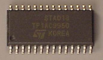
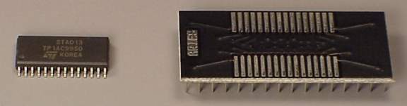
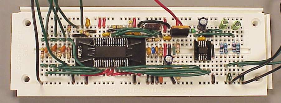
Connecting The ChipThe first problem with using the STA013 for a prototype MP3 player is that it is a surface mount part. Unfortunately, it is not made in any through-hole packages. The two basic approaches are to buy or make an adaptor board, or to solder wires to each pin.
Aries makes adaptors that are ideal for connecting the STA013 in a prototype, which DIP pins are easier to use. The adaptor shown in Figure 2 is available at DigiKey (P/N: A323-ND). This is actually a 32 pin adaptor, so 4 pins are unused with the 28 pin STA013. While an adaptor circuit board is easier, it is also possible to solder wires to all the pins. Here's a student project by Peter D'Antonio and Danial Riiff, with 28 wires soldered. TODO: contact Peter and Daniel (anyone know their email address??) to ask for permission to display their soldered wires photo. Update: Scott McNab wrote this nice page with instructions to make your own adaptors. Power Supply Issues, 5 Volt to 3 Volt InterfaceThe STA013 is a 3 volt chip. The data sheet claims is can run between 2.7 to 3.6 volts (and separately mentions 2.4 volts for some unknown reason). It must not be used at 5 volts. Creating a 3 volt power supply is not difficult. Interfacing the 3 volt STA013 to 5 volt microcontrollers and DACs (CS4334) requires attention to make sure that they are properly received and to prevent damage to the 3 volt STA013. If your player uses a 3 volt microcontroller and 3 volt logic, then there is nothing to worry about and you should skip this section. If a 5 volt microcontroller is to be used, there are some simple ways to connect the chips, as long as the microcontroller inputs have TTL compatible input thresholds (nearly all microcontrollers do).Connecting the STA013 output pins to TTL level input pins is simple, because the STA013 will output at least 85% of it's power supply for a logic high, and a maximum of 0.4 volts for a logic low. Even if the STA013 is run at 2.7 volts, it will still output 2.3 volts, which will satisfy the 2.0 input requirement of a TTL level input pin. The four CS4334 input signals are all TTL level.
The outputs from a 5 volt powered chip must not be directly connected to the STA013 input pins. The STA013 inputs are not 5 volt tolerant. Each pin has a pair of input protection diodes. These diodes may conduct a small current. The simplest and easiest way to interface a 5 volt output to the STA013 input pins is with a series resistor, that will limit the current when the 5 volt output is high. There is some input capacitance (3.5 pF) on the input pins, so adding a small capacitor in parallel with the resistor will allow the rapid edge to properly drive the input pin. The value of the resistor and capacitor are not critical, Figure 4 shows 4.7K and 47pF, which limits the steady-state current to less than 1/2 mA, and has been tested. The capacitor is not really necessary if the pin doesn't need to be driven rapidly, such as the RESET pin.
Connecting the SDA signal from a 5 volt microcontroller to the STA013 is a bit more complex, though a simple circuit can often be used. The SDA line is bidirectional, where either device can pull down, and a resistor provides the pull-up. Most microcontrollers have TTL thresholds, so a pullup to the 3 volt supply will easily satisfy the 2.0 volt input high requirement. If the microcontroller will never drive the line high (only pull low or tri-state), then no other parts are probably required. This may be the case if the microcontroller has a dedicated I²C pin. In most cases, the microcontroller can drive the line high, and an additional resistor should be added to prevent damage to the STA013. This current limiting resistor should be small, as it will form a resistor divider with the pullup when the microcontroller drives low. If the pin can be put in a tri-state mode, the firmware should be written to use the tri-state for a logic high, or at least tri-state the SDA signal when not transmitting data, to save power.
Philips suggest a somewhat more complex 5V to 3V connection involving a pair of mosfet transistors. Their solution is a much better approach for a general purpose bus. The pair of resistors shown here should only be used with a single microcontroller and the STA013. If you have a N-channel mosfet transistor, the Philips circuit would be better. This is only necessary on the SDA line, since the microcontroller will always generate the clock, so the circuit in Figure 4 will work well for the SCL signal. Where to Connect The PinsThe good news is that thirteen pins connect to ground or the +3 volt power supply, five connect to simple resistors, capacitors, and the crystal, leaving you only ten pins to worry about. These 10 signals can be grouped into four categories:
The resistors connected to PVDD and PVSS are 4.7 Ohm (not 4.7k). Any value near a few ohms is ok, if 4.7 ohms is not available. The capacitors connected to the crystal may need to be changed to match the resonance of the crystal. Values are usually in the range of 15 to 47 pF, and many crystals are not very sensitive to the exact capacitor values used. The inductor shown on the CS4334 power supply is intended to block noise from digital circuitry that's also connected to that line. The value of the inductor is not critical, so 100 µH would probably work well. In no inductor is available, and alternative is to create a separate ("clean") supply for the CS4334 with a LM7805 or similar linear-mode voltage regulator. From Deckx Kevin: Here's a table listing how each pin should be connected, which can be used as a "check off" list while wiring the chip on a breadboard.
Communication And Configuration Via I²CThe STA013 requires initialization by I²C communication. This step can not be avoided. Part of the required initialization is to send a group of 2007 writes provided by ST in the file p02_0609.bin. A frequently asked question is "do I really need to use I²C and the file from ST?". The answer is Yes!, the STA013 will not work without being properly initialized. The config file from ST is part of this process. There does not appear to be a way to make the chip work properly without it. Fortunately, the initialization step isn't difficult, and you will find working example code at the end of this page.First, a little background about I²C. I²C is a 2-wire protocol, created by Philips. One line acts as a clock (SCL) and the other data (SDA). The protocol defines the ability to have multiple masters initiate communication, but here we'll only worry about the simple and common case where the microcontroller is the only device that controls the bus, and all the other chips (like the STA013) respond to queries initiated by the microcontroller. There are many sites with detailed info about this protocol.
Simple I²C, Four Basic OperationsFor simple applications (like using the STA013), there are four fundamental operations. Only these four operations are needed to build routines that access the STA013 chip:
Reading From The STA013, "sta013_read" FunctionUsing these four basic I²C operations, a function to read from the STA013 can be built as follows:
Writing To The STA013, "sta013_write" FunctionWriting to the STA013 is even easier. Here are the steps.
There are other faster and somewhat more complex ways to communicate with the STA013, such as writing to multiple consecutive locations. These optimizations are usually of little benefit with the STA013. Actually Using These Functions To Configure The STA013Now that you've read (or perhaps skipped over) the above section about basic I²C routines, from here forward "writing" will mean writing a byte to a particular address using the steps of "sta013_write" and "reading" will mean reading a byte from a particular address, using the steps of "sta013_read".The first step should be to check that the STA013 is actually present. Just read from address 0x01. If the read routine returns with an error, then no device sent an ACK bit and there is no chip installed. If there is an ACK, the data returned should always be 0xAC. Any other value means that the STA013 (or the code implementing the communication) isn't working properly. It is also possible to read the STA013 revision code at address 0, but ST gives not useful info about what this means, so it's probably not worth the trouble. The important step is to verify the ACK and 0xAC data at address 1, which means that the STA013 is present and communicating properly. If you don't get the ACK, check the connections to the STA013, and verify that the STA013 got a good reset pulse and has its crystal oscillating. The next step is to transmit the "p02_0609.bin" config file provided by ST. This file consists of 2007 address and data pairs. Sending the file is simple, just write a loop that passes each pair to the "sta013_write" function. Each ACK should be checked and the process aborted if any write doesn't receive any of its ACKs. The exact purpose of the p02_0609.bin file is a bit of a mystery. ST calls it a "config" file on their website. In the app note, they describe it as a "Patch File". Most of the addresses used in the file are registers that are not defined in the data sheet. Probably only a few engineers at ST, who've certainly signed NDAs, really know what this file does. If you, dear reader, have any solid information (not guesswork or speculation), please contact me so I can update this section. Also, if you manage to get a STA013 chip running properly without using p02_0609.bin, please send me an email with details and the date code from your chip, so that I can update this page. Update: a couple people have reported being able to play low-bitrate files without loading the p02_0609 data.
Update, March 15, 2001: burried deep within the p02_0609.bin is a write to address 16. Address 16 is the soft reboot regsiter. A brief delay is probably required after writing to this register. I've found that the vast majority of STA013 chips work without this delay, but some don't initialize properly and their data request pin stays stuck either high or low. The example code below does not have this delay, and it worked properly with the chip on the protoboard shown in the photo. Hundreds of these chips have worked without this delay on the MP3 player boards, but a few have not been so fortunate. Many people have reported success designing with the STA013 based on this page. This problem appears to be rare, but it does happen. It may be more prone to happen with a really fast mircocontroller, like the Atmel AVR or some 16 bit chips. Code with this delay will appear in the MP3 player's 0.6.2 firmware release, inside the "drivers.asm" file. If you're having a similar problem before the 0.6.2 release, contact me for the code. It's just a simple 0.6 ms delay after sta013_write if the address was 16. Also in 0.6.2 is some code which sends a tiny 1/2 second MP3 of silence to the STA013 and measures how long it takes for the STA013 to consume it. This appears to be the only effective way to detect if a STA013 has been misconfigured, as it will properly respond to I²C queries while it's in this funny state.
Update, April 4, 2010: Raghavendra Talekar send this message with insight about the likely origin and purpose of the config file. The p02_0609.bin file is actually a simple ASCII text file. Why ST used a ".bin" extension is also a mystery. Each line contains two numbers, the first is the address and the second is the data to write to the chip. Here's the first several lines of the file:
The example code near the end of this page contains a perl script to convert this data format into intel-hex, which can be programmed into a EEPROM or downloaded to a monitor program. The perl script also adds a length count and simple checksum, which can be used to check the data before sending to the the chip. Once the config file is sent, the board specific settings must be sent. Here are the settings used in this example, for 14.7456 MHz crystal and the CS4334 DAC:
It is possible to use the STA013 with other crystals. For example, to use a 10 MHz crystal, use the values in Table 5 from datasheet, and to use a 14.31818 MHz crystal, use Table 7. ST also provides a ConfigPLL v1.0 utility to compute these parameters for other crystals. It's interesting that register 7 is shown in ConfigPLL, but not in the tables of the datasheet. ConfigPLL seems to always set it to zero. Likewise, the tables list register 5, but ConfigPLL does not. All the tables show register 5 at 161, so perhaps that's the right setting for any crystal. One thing is certain, the settings shown here (same as in the example code) have been tested and are known to work with the 14.7456 MHz crystal and CS4334 DAC, so using them with 14.7456 MHz and a CS4334 is a very safe bet! The easiest way to send these setting it to just add them on to the end of the p02_0609.bin file, and let the loop that sends that file do the work. The last several lines of that file are actually writes to some of these registers, so they can be removed and replaced with the configuration you need. The copy of p02_0609.bin in the download section has these settings added, so you can use it with a CS4334 and 14.7456 MHz crystal without any changes. After you've checked the 0xAC, and sent the config file (with config data appended), then all that's left it telling the chip to start running. This could perhaps be added to the config file as well, though the example shown below does it separately. Just write a 1 to address 114 to tell the STA013 to start running, and then a 1 to address 19 to tell it to start playing. The DATA_REQ pin should be asserted, and when you start feeding valid MP3 data in, the chip will detect the MP3 sample rate, create the correct clocks for the DAC, and start pushing data into it. Sending MP3 DataSending MP3 data to the STA013 is simple. The basic idea is to give the STA013 data when it requests more. You do not need to be concerned about the MP3 bitrate, the STA013 chip will determine what the bitrate is, consume the data at the correct speed, and give you the request signal when it needs more. As you transfer the bits, it will end the request when its buffer is nearly full. Variable bit rate files are automatically handled. It also automatically detects the required sample rate (44.1 kHz, 48 kHz, etc) from the MP3 data and automatically adjusts the DAC clock. All you have to do is give it more data when requested. The speed that you actually input the bits doesn't matter, usually you'd send them as fast as possible, as long as it's under 20 Mbit/sec.The STA013 is designed so that your project never needs to "know" anything about the MP3 file. When the chip requests more data, you need to respond in a timely manner, and feed the data in as rapidly as possible until the STA013 de-asserts its request signal. The chip will make requests more frequently at faster bitrates. The combination of your response time and data rate, if they are slow, may limit the maximum bitrate that can be played. The good news is that most VBR encodings only use fast bitrates (256 and 320 kbps) for brief times, so in many cases the STA013's input buffering will allow a design that couldn't supply 256 kbps contant bit rate to play variable bit rate files which contain brief bursts at these high speeds. The STA013 will ignore non-MP3 data (producing no sound), so it's safe to feed entire MP3 files, which may contain ID3 tags, into the STA013 without concern for which part of the file is MP3 bitstream and what portion is the ID3 tag. The chip will just keep requesting more data until it sees valid MP3 information. It's also safe to feed damaged MP3 streams into the STA013, for example truncated files due to partial download. Most damaged MP3 data is completely ignored. Some damaged files will produce a brief chirp sound (usually depending on what follows immediately after the damaged part), but the STA013 will rapidly sync back to good data that's sent after a corrupted part. One final thing to keep in mind is that the STA013 doesn't "know" about files. You may decide to issues I²C commands between each file, but that is not necessary. A simple player may just send the contents of file after file to the chip, and the STA013 will automatically adjust its settings when it sees data that specifies a different bitrate, sample frequency, mono or stereo mode, etc. This section was contributed by Ed Schlunder (zilym@NOSPAM.yahoo.com). Ed's examples are written in C. I'll add a comment or two in this smaller green text. There are three signal lines used for sending the MP3 data to the STA013 decoder: SDI (DATA), SCKR (CLOCK), and DATA_REQ. The STA013 asserts the DATA_REQ line when more MP3 data is needed from the host controller. The host controller then feeds MP3 data, most significant bit first, on the SDI line. Each bit placed on SDI is clocked, by the controller, into the STA013 with the SCKR signal line. Some example code for sending MP3 data follows:
The example code near the end of this page has a very similar function named "xmit_mp3_clip" implemented in 8051 assembly. It contains 8 copies instead of a loop, which nearly doubles the speed. Also keep in mind that if something goes wrong with the STA013 and it doesn't assert DATA_REQ, this will turn into an infinite loop. For a "real" player design, some sort of timeout should be added. The above code assumes that whenever the STA013 asserts DATA_REQ, it can accept at least eight bits of data. The STA013 datasheet never explicitly says this is the case (AFAIK), however, in the practice it does seem to hold true. Which is very good, because this lets us use the 8051 serial mode 0 to send data more efficiently... In 8051 serial mode 0, the RxD pin shifts data out of the serial buffer (special function register SBUF) as the TxD pin provides clocking for each bit transmitted. If you hooked the STA013 SDI pin to the 8051 RxD pin and STA013 SCKR to 8051 TxD, you could in theory now use the 8051's UART hardware to do the bit shifting that we had to do manually in the code example before. However, there's a catch: the 8051 UART shifts out data least significant bit first, which is the opposite of what the STA013 is expecting. Therefore, before writing a byte of MP3 data to the SBUF register, we must reverse the bits so that the STA013 receives the bits in the order it expects:
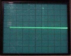
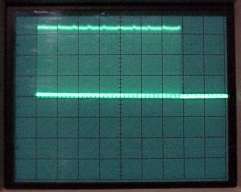
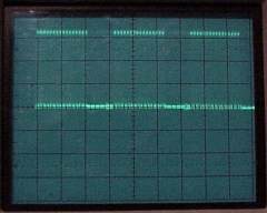
The lookup table should be implemented in code-space (MOVC). The 8051 serial mode 0 is so fast that the checks on the TI bit are unnecessary... you can't get the data and do a fast table lookup bit swap before all of the previous bits are sent. My old player design used this approach, and you can look at it's code, including the "flip_bits" lookup table, to save you the effort of regenerating this table. Look at the code in "idle_loop" for a timing analysis, best case is 13 cycles, and 8051 mode 0 takes 9 cycles to transmit. A microcontroller with a dedicated SPI port would be even better because the SPI interface will send data in the proper bit order by default. So, use SPI instead of you have the option. End of Ed's section. Thanks Ed, that really helped. The fastest and most efficient method, but also by far the most difficult to design, is to build dedicated hardware to send large blocks of data to the STA013 automatically, without any CPU overhead. The new MP3 player does this using a Xilinx FPGA chip. The basic idea is that the CPU writes the address and length of a block of MP3 data that resides in memory, and then writes to a "go" bit. The hardware automatically detects when the CPU doesn't need to access the memory, and reads the MP3 data into a shift register, which sends the bits to the STA013 as it requests them. The bits are shifted at about 7 Mbit/sec (very fast, but the STA013 can handle 20 Mbit/sec). Each time the shift register is empty, the hardware makes another read from the next memory location, as soon as there is an opportunity to access the memory when the CPU doesn't need it. When all of that block has been sent, the hardware gives the CPU an interrupt, so that the CPU can give it the next block's addr/len to transmit. For some more details about how this is done, take a look at the memory map page for the new player design. This design allows even a slow (low power) CPU to easily play the fastest MP3 streams (320 kbps), but it is a very difficult approach. While it is possible to design a very high performance data transfer, the example code below uses the simplest possible method, directly manipulating the port pins. The intention of the example code is to be simple and easy to understand. STA013's Input Buffer CapacityA common question about the STA013 chip is "how big is the input buffer?". ST's datasheet isn't much help, but with a really fast transfer to the chip and a slow MP3 bitrate, we can try to measure it. Figure 7 shows the fast SCKR signal generated by the dedicated hardware used in the MP3 player board shown at the rest of these pages. A 64 kbps/sec MP3 file was being played during this test, to limit the number of bits played while the DATA_REQ signal was asserted and each burst of data was loaded.
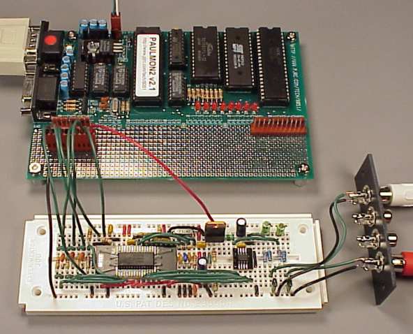
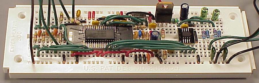
The left photo shows a burst of transfer every 26 ms, which suggest that an average of 1664 bits are transfered into the buffer each time, to maintain 64 kbps throughput. Our sony mavica camera uses approx 15 ms shutter speed in this lighting, which made the left photo very difficult... it's either a way-too-bright spot a few divisions long, or a weak image if the shutter happens to open between traces (as in the one I finally ended up using). That's why you see a weak trace, when a slow sweep is usually a bright and annoyingly flashing image. The center photo shows that the bursts are about 345 µs long. The right photo shows the effective bit rate. Bursts of 16 bits are sent at 7.37 MHz, with a delay between each 16 bits while the control state machine arbitrates for access and then reads the DRAM. 32 bits are sent in approx 6.4 µs, for a bit rate of 5 Mbit/sec, which suggests about 1725 bits are loaded into the STA013's input buffer during the 345 µs burst. This second method probably over-estimates the buffer size slightly, since the control state state machine must sometimes wait during the bus arbitration (the slight "ghost" image in the right photo), causing the effective bit rate to be somewhat less than 5 Mbit/sec. Still, 1664 and 1725 bits is a 3.7% error (if you assume 1664 is closer to the truth)... not bad for counting divisions on the 'scope screen! These waveforms only measure the input buffer between the point where the STA013 asserts and releases DATA_REQ, which is says that the buffer is at least 206 bytes. Simple Example SystemTODO: draw schematic that exactly matches breadboard wiring... very similar to figure 6, add LM317 and 3/5 volt interface parts (figures 3,4,5), re-label I/O with 8051 port pin names. For now, check the ASM source comments for which port pins connect to what signals.TODO: write some descriptive text... the pictures show what it looks like and the screen dumps shown how to run with PM2 monitor. See comments in the code for making a stand-alone version or using with a different development system.
Here's a typical session using the example code. The code is written to run with the PM2 monitor program. It can be easily modified to run under a different development system, or stand-alone. See the comments in the source code for details. The example uses the 8051 development board. Here, the board is booted and the memory and flash are cleared. It's not really necessary to clear the memory, but if anything is residing in the flash memory (other than MP3 data), it must be erased.
Three files must be downloaded. The "sta013.hex" was sent first in this example (794 bytes of data). Then the "p02_0609.hex" file was transmitted next, and finally one of the MP3 test clips was sent. In this example, it was "faith_hill_clip.mp3", which is several seconds from a well known song. The example code uses the following memory:
Any MP3 data could be downloaded, but the four test clips in the download section are encoded at very low bit rates, so that a 32 kbyte clip can play for several seconds. At the usual 128 kbit/sec MP3 bitrate, 32 kbytes will play for only 2 seconds.
Once all three files are loaded into memory, just run the program. The example code does some checks to make sure that a valid STA013 config file is present. It does not check the validity of the MP3 data... whatever is in the 0x8000 to 0xFFFF memory range is sent to the STA013 chip.
Downloadable Free Code And Supporting Files
Testing and troubleshooting custom-built circuitry can be difficult and frustrating. The idea behind these MP3 clips is to provide a ready-to-use test for the STA013 and this example code, already converted to intel-hex format for loading into the flash. If data is sent to the STA013 that's been incorrectly translated, it will detect that it's not a valid MP3 stream and do nothing. Having known-to-work MP3 test clips in the correct format eliminates (or at least reduces the likelyhood of) one more potential source of trouble. All four of these intel-hex format clips were tested on the example hardware shown. These four MP3 clips are short sections of well-known copyrighted works. I believe that providing these clips is a fair use of the copyrighted material, because the purpose and character of the use is educational, the amount and substantiality of the portion used in relation to the copyrighted work as a whole is a 5 to 8 second clip of a 3-5 minute song, and the effect of the use upon the potential market for or the value of the copyrighted work is effectively zero. AVR, PIC, HC11 & Other MicrocontrollersI receive a good number of emails from people using these other microcontroller chips (usually Atmel AVR and Microchip PIC), where they have problems using the STA013. The most common description involves the I2C able to read 0xAC, but the chip doesn't begin operating and assering the demand signal after they download the file and give it the run command. If you are in this situation, and you're read this page, the ST datasheets, and looked your code over and over, and you are completely stuck, there are two basic approaches you can take:
TODO: add a wrap-up section, with some suggestions about what to do next, links to new and old player.
| ||||||||||||||||||||||||||||||||||||||||||||||||||||||||||||||||||||||||||||||||||||||||||||||||||||||||||||||||||||||||||||||||||||||||||||||||||||||||||||||||||||||||||||||||||||||||||||||||||||||||||||||||||||||||||||||