|
|
| ||
|
Shopping Cart
|
| Home | Products | Teensy | Blog | Forum |
|
You are here:
MP3 Player
|
|
|
Applications For The Player
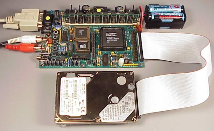
Car audio systems will also make use of the line level outputs. The board is designed with an on-board switching power supply capable of operating a laptop type hard drive. The power supply has an pre-regulator circuit which can withstand the large voltage spikes that can occur in a car's 12 volt system.
Portable applications will use the headphone amp, and must run
from batteries. The on-board
switching power supply is designed to operate from four AA size
cells. The large DRAM buffer is intended to allow the drive
to remain in sleep mode, to maximize battery life.
Controlling The PlayerThe board has six pushbuttons, with the following functions:
When the LCD is connected to the MP3 player, its 12 additional pushbuttons can be used to control the player. The 6 original buttons continue to function, but their functions are duplicated by the 12 buttons. The 12 buttons also provide on-screen navigation. The LCD User Interface Page has details of how the LCD screen menus function.
It's also possible to control the operation of the player by sending commands to it on its serial port. The serial port is available on both the 9 pin D-Sub connector, and on the 4 pin LCD expansion port. Getting Files Into the PlayerThe firmware reads a standard FAT32 formatted partition. It does not use a linear "raw sectors" approach like the original MP3 player design.Using MS Windows, you format the drive with FDISK.EXE and FORMAT.COM. It's important to answer "yes" to the "Enable Support For Large Disks", so that the drive will be formatted using FAT32 and not FAT16. Then you just copy the MP3 files to the drive, using Windows Explorer, or whatever other program you like. Update, 4 Feb 2001: Firmware 0.6.0 supports fragmented FAT32 volumes. It only reads from the main directory, but it includes new FAT32 code that will allow upcoming version to be built to support reading subdirectories. Prior firmware requires the files all be located in the main directory, and that you run DEFRAG to fully defragment the drive. We are planning to develop a kit that essentially makes the player a removable hard drive. The kit will include two small boards, one to mount to the side of the player and one to mount inside the computer's drive bay, with mating 50 pin "Centronics" connectors. The computer will supply power to the player, and the player will detect that it is inserted into the computer and tri-state all of its IDE signals, so that the computer will not "see" the player, only the drive. Without this arrangement, the primary method to put new files on the drive is to remove it from the player and put it into your computer. With a large drive, this may not be necessary very often, compared to a small memory flash-based player where the files are shuffled frequently. Power Source For the PlayerThe board has two power inputs, a DC power jack that accepts unregulated voltage between 9 to 15 volts DC, and a 2 pin header that accepts unregulated voltage between 4.5 to 6 volts. The higher voltage input is intended for use from an AC adaptor or a car's 12 volt electrical system. The lower voltage input is intended for four AA batteries, or from a 5 volt power supply.The board features an on-board switching power supply, which can operate a laptop hard drive. To use a standard 3.5 inch hard drive, an external power supply is required to provide power to the drive. The on-board supply is primarily intended to allow operating a laptop drive from batteries or a car's 12 volt system. The on-board supply has a software shut-down feature, so that the firmware can shut off itself off automatically after a period of inactivity. It is possible to build the board without the power supply. If this is done, an external supply must provide both 5 volts and 3.3 volts regulated to the board. See the pinouts and power supply connections page for more information about how to connect power to the board. Buffer MemoryThe player is designed to use a 72 pin SIMM, at 4, 8, 16 or 32 megabytes. For battery operation, this limits the power consumption by allowing the drive to stay in its sleep mode most of the time. Likewise, in a car this means the drive can remain in sleep mode with the spindle stopped and the drive heads parked, where it can survive a much greater mechanical shock. The buffer memory is also used to store a list of files and subdirectories (up to 5 levels deep).Update: April 22, 2002: The 0.6.x firmware uses the SIMM to buffer a single MP3 file. If the file does not fit entirely in the available memory, the portion that did not fit is not played. Because of this, it's advisable to use at least an 8 or 16 meg SIMM that can buffer an entire file. Better memory usage is planned for the 0.7.x firmware, including buffering multiple upcoming files (for more rapid response to pushbuttons) and playing files smaller than the SIMM. The board is designed to use standard 72 pin SIMMs that follow the specs in this Micron data sheet. Most older used SIMMs with 8 or 9 chips on each side follow these specs. Some newer SIMMs use a different wiring that only allows a portion of the SIMM to be accessed on this board, and in some cases can be problematic. Sadly, there is no simple way to tell which type of wiring a 72 pin SIMM uses, other than trying it with the player. In general, older SIMMs are more likely to work at full capacity. Access speed (60ns, 70ns, etc) and access method (EDO vs FPM or non-EDO) does not matter. The player can also be used without a SIMM. If the firmware can not find memory installed, it will automatically run an older version of the code which does not make any use of the SIMM memory.
Physical Size, Board and Drive MountingThe assembled board is the size of standard hard drive. The board's dimensions are 5.75 by 4.0 inches, with the tallest components measuring 0.9 inches height from the top surface of the board. When a 72 pin SIMM is installed, it's top surface will typically be higher than 0.9 inches above the board, so and space planning for mounting the board should consider the height of the SIMM to be installed.The board offers 4 mounting holes in the corners, sized for use with #6-32 size machine screws. Four additional mounting holes are provided on the top and bottom edges to mate with the standard hole positions found on the bottom of a standard size hard drive. There are also another 4 mounting holes intended to mate with a laptop size hard drive. The area under the laptop drive contains no tall components, which allows the laptop drive to be mounted between 0.375 to 0.5 inches above the board. The board provides both a standard 40 pin IDE connector and a 44 pin laptop IDE connector. The 4 additional pins on the laptop connector provide power to the laptop drive. For a standard drive, an external power supply is needed to drive the 4 pin power connector on the drive. Upgradable DesignThe board is designed to be flash upgradable. New firmware may be loaded into the board by the user. See the firmware upgrade instructions page for detailed instructions. As new features are added to the firmware, existing boards may be easily upgraded by the user. The firmware download page has a description of the features offered by the firmware, and a list of what features are planned for upcoming firmware revisions.Open SourceThe firmware source code is available under the terms of the GNU General Public License (GPL). You may copy and modify the firmware under the terms and conditions of the GPL.The entire circuit board schematic is published, as well as schematics for the circuitry implemented by the FPGA. Expansion PortsThere is a 4 pin connected, which is intended for connecting a board and an LCD Display and additional pushbuttons. This connector basically just provides +5 volt power, and the transmit and receive signals of the serial port. The display board will have a small microcontroller which communicates with the main board, parsing display messages and putting them onto the LCD display, and scanning for pushbutton presses and sending them to the player.There is also a 34 pin bus connector in the center of the board. This may be used to someday allow add-on boards with high-speed download, wireless download, etc. There are no firm plans at this time for any add-on cards. We will of course help you if you'd like to design an add-on card. |