|
|
| ||
|
Shopping Cart
|
| Home | Products | Teensy | Blog | Forum |
|
You are here:
8051 Tools
|
|
|
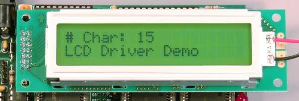
Example Code To Use The LCD Display
Here are several examples of how to use the LCD port with any standard character LCD.
How To Access The LCD RegistersThis section describes how to directly access the LCD registers. It is not difficult, but if you only want to print normal text to the LCD, using the example code above is the easiest approach. However, if you have special needs, or you want to understand how the example code works, or you want to write your own driver for the LCD, then this section is for you.
The LCD is accessed using four memory mapped registers. Here
are definitions to use in your code:
Status Register and Busy CheckBefore writing to the LCD, you must wait for it to be available to receive data. Usually, it will not be busy, but there are times when it is performing internal operations and you must wait.To check if the LCD is busy, simply read the lcd_status_rd register and check the most significant bit. If this bit is 1, the LCD is busy and you must wait to write. If it is a 0, then the LCD is ready.
The lower 7 bits of the status register return the current address pointer. Normally, your code would set that address and "know" what it is by how many characters have been written, so the address read feature is rarely needed or used.
Commands For The LCDOnce the LCD is not busy, you can give it a command by simply writing a byte to the command register. There are many commands available. All commands are a single byte requiring only one write operation.
When first initializing the LCD, you would write the 0x38 command first. This configures the interface for 8 bits, enables both lines, and sets the font to 5x7 pixels which is the correct size for most LCDs (if you have a rare 5x10 pixel LCD, you would change this to 0x3C. Normally, the command 0x0C is written to turn on the LCD and disable showing a cursor. However, if a solid or blinking cursor is desired, one of the two lower bits may be set. Then, the shift mode command is sent, usually to 0x10, to disable shifting the display and instead simply moving the cursor. This makes the LCD operate in a manner similar to a computer screen, where the characters stay where you put them and the cursor moves forward. However, you can turn on the shift mode to make the LCD act like a reader board, where your characters always appear at the same place and the whole display shifts every time you write a character. Before writing to the display memory, the command to set the address in the memory is usually sent. On most 2 line LCDs, address 0x00 (command 0x80) set the cursor to the beginning of the first line, and address 0x40 (command 0xC0) sets the address to the beginning of the second line. Writing to the DisplayOnce the LCD is initialized, you make it display text by simply writing to the lcd_data_wr register. The position where the character will appear depends on the current address, which you set with Set Display Buffer RAM address command. Remember that there are 128 possible addresses, but only 40 of them will correspond to on-screen display on a 20x2 LCD.Writing bytes 0x20 to 0x7D will display ASCII characters. Many LCDs render arrows for 0x7E and 0x7F, and a variety of other symbols and characters from 0x80 to 0xFF. Bytes 0x00 to 0x0F will render user defined characters. Each time you write to lcd_data_wr, the display address will be incremented or decremented, depending on the shift mode. It is also possible to read the contents of the display buffer RAM, though this is rarely done. Creating Your Own Custom CharactersBy sending the Set Character Generator RAM address, you can access a small RAM used to load custom characters. All writes to lcd_data_wr will write into the custom character RAM rather than the display buffer RAM, so you will need to issue the Set Display Buffer RAM address after you have finished loading your custom characters.In 7x5 pixel mode, eight custom characters can be stored. Each takes 8 bytes of memory, where only the lower 5 bits are used and the 8th byte is unused. After loading your custom characters, you can cause them to display by writing bytes 0x00 to 0x07. More InformationThe Hitachi HD44780 Datasheet is a complete reference for the operation of the controller chip on most character mode LCDs. LCDs with this controller chip, or compatible chips from other manufacturers, are very common. Here are links to other excellent pages with information about using the controller chip:
If you know of other sites that should be on this list, please contact me. |