|
|
MP3 Player Kit, Assembly Instructions
These eleven assembly diagrams are also available as high resolution
TIFF files.
Step 1, Solder Surface Mount ICs
Step 1, Component List
| Quantity | Color | Components |
|---|
| 1 | . | STA013 MP3 Decoder IC, 32 pin SOP Package |
| 1 | . | CS4334 24 Bit Digital to Analog Converter IC |
| 1 | not shown | MAX810-3.0, SOT-23 Package |
Step 1, Notes
These SOIC surface mount chips should be soldered before any
of the nearby through-hole components are added. The nearby
parts can obstruct your access to these tiny pins, making it
much more difficult to properly solder these parts.
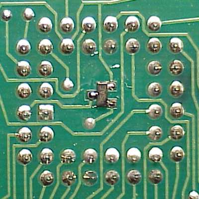
Step 1, MAX810, Solder Side
The MAX810 chip is surface mount soldered to the solder
side (bottom) of the board. It is located under the
center of the 87C52 chip.
|