Tutorial 3: Serial Monitor & Input
In this section, you will use the serial monitor to see more information about what your program is doing. You will also use pins in input mode to receive signals, which allows your code to respond to real world events!Materials Required
- Teensy 4.0 with Pins
- Tutorial Parts Kit
- Solderless Breadboard
- USB Cable
- Wire Stripping Tool (#22 size)
- Computer with USB
- Multimeter or Voltmeter
Serial Monitor & Serial.print()
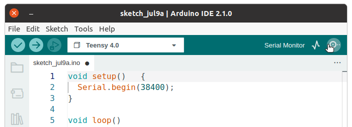
You can send messages to the Serial Monitor window on your PC or Mac, which is very helpful to see what your program is doing. Here is a simple example.
void setup()   {
  Serial.begin(38400);
}

void loop()
{
  Serial.println("Hello World");
  delay(1000);
}
Inside the setup function, "Serial.begin(38400)" initializes the communication. The number 38400 is the baud rate. The Teensy always uses USB speeds, so this number doesn't matter.
Then you can use Serial.print() and Serial.println() to send information. This example just sends "Hello World" every second.
To actually see the messages, click the Serial Monitor button (last in the toolbar).
The Serial Monitor window should appear, with these messages printing as your program runs.
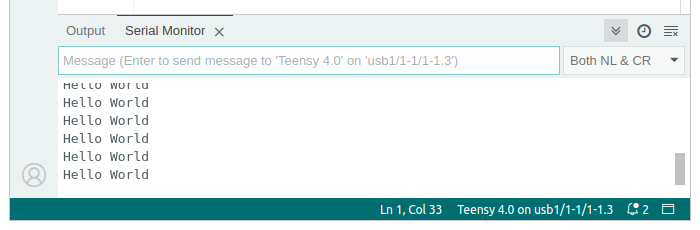
Simply printing "Hello World" isn't very interesting, but as you create programs that do different actions based on real world input, Serial.print becomes much more useful.
Connecting A Pushbutton
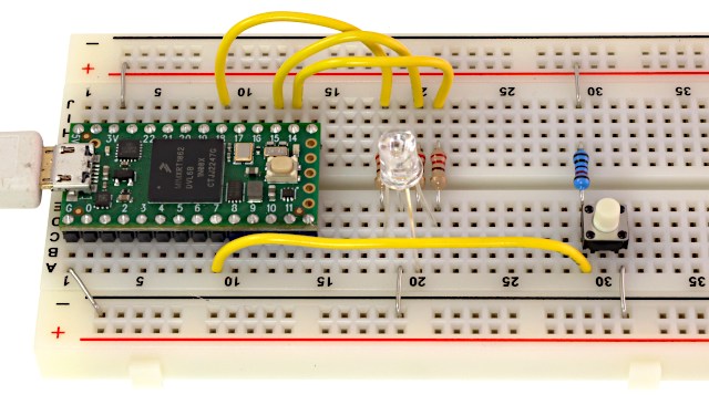
Pushbuttons are simple but very useful input. To connect a pushbutton, you will also need to connect a pullup resistor.
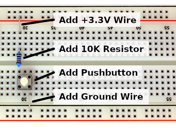
When you press the pushbutton, it connects to ground. When you release the pushbutton no longer connects. The resistor provides 3.3 volts on the pushbutton pin. Without the resistor, the voltage could remain at zero or randomly fluctuate due to even weak electronic interfence from power lines or radios. It is called a "pullup" resistor because it serves to pull the voltage back up when you are not pressing the button.
You can verify the circuit works by connecting a voltmeter. As with the RGB LED, testing your connections before writing code is good practice. Verifying the hardware works before you dive into the software can save time and frustration.
The voltmeter red lead connects to the group of 5 breadboard holes where pushbutton and 10K resistor meet. The black lead connects to ground.
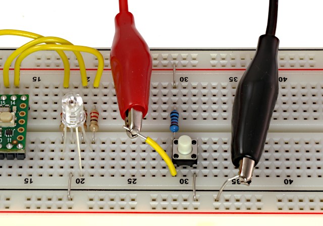
Here is what you should see on the meter. The exact voltages may vary slightly, but should be close to 3.3V and zero.
| Button Not Pressed | Button Pressed |
|---|---|
 |
 |
It may seem strange to have zero when the button is pressed and have 3.3 volts when it is released. This is called "active low", because the signal is low when the condition is happening. Active low signals are very common practice in electronics, especially for pushbuttons.
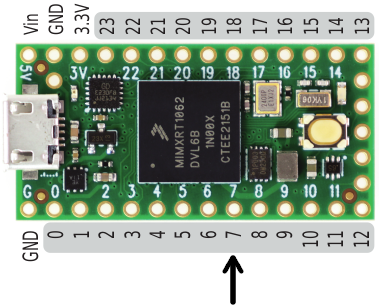
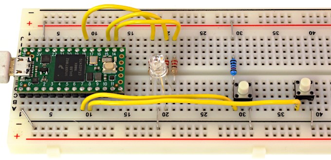
When you are confident the pushbutton circuit works, just connect it to any unused pin. In this photo, it is connected to pin 7.
Using digitalRead
To read the pushbutton, you must first use pinMode to configure the pin to work as an input. Then you can use digitalRead to actually read the pin. Here is an example.
void setup()   {
  Serial.begin(38400);
  pinMode(7, INPUT);
}

void loop()
{
  if (digitalRead(7) == HIGH) {
    Serial.println("Button is not pressed...");
  } else {
    Serial.println("Button pressed!!!");
  }
  delay(250);
}
In this example, the "if" statement is used, together with "else". The condition after "if" is tested, and either the code in the first or the second set of curly braces is run.
Using digitalRead(7) will result in either HIGH or LOW. This code compares digitalRead(7) to HIGH using the "==" comparison. A subtle but very important detail is the double equal. Using only a single equal attempts to write or assign a value, which would be silly since you can't change what digitalRead(7) found. A double equal means to compare 2 numbers, rather than set the first equal to the second.
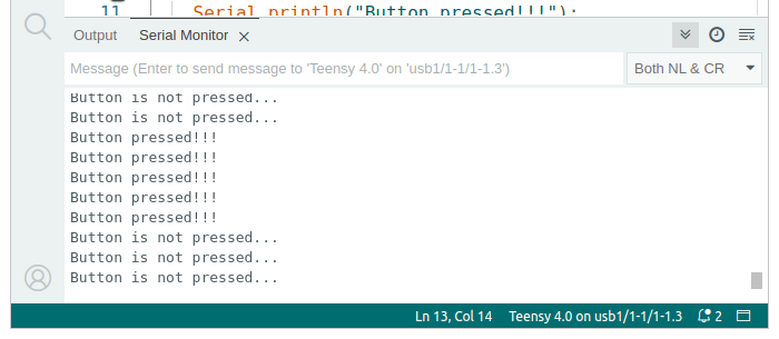
When you run the program and use the Serial Monitor, you will see messages that change when you press the pushbutton.
Built In Pullup Resistor
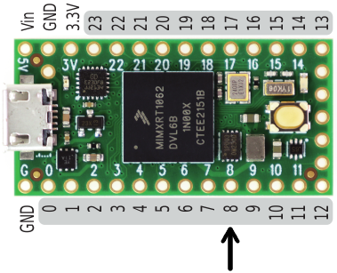
Use of pullup resistors is so common that Teensy provides a pullup resistor on every pin, built inside the chip itself.You can connect a second pushbutton by just wiring one side to ground and the other side to a pin (pin 8 in this example). One disadvantage of the built-in pullup is you can not test the pushbutton with the voltmeter before wiring it to your Teensy.
You can activate the pullup resistor by using INPUT_PULLUP with pinMode in your setup function.
void setup()   {
  Serial.begin(38400);
  pinMode(8, INPUT_PULLUP);
}

void loop()
{
  if (digitalRead(8) == HIGH) {
    Serial.println("Button is not pressed...");
  } else {
    Serial.println("Button pressed!!!");
  }
  delay(250);
}
Usually when using the pullup resistor, you will turn it on with INPUT_PULLUP and leave it on. However, you can turn it on and off. When the pin is in input mode, you can turn the pullup resistor on and off by using digitalWrite. That isn't very intuitive, writing to a pin which is input mode, but that is how it works. INPUT_PULLUP is a Teensy extension. On regular Arduino boards, digitalWrite the only way to access the pullup resistor.
Pushbuttons To Control LED Colors
You can use digitalRead to make your programs respond to pushbutton input. Here is the Red/Green color fade example from Tutorial 2, but with another variable added so it has 2 modes, fading from Red/Green and Red/Blue. The pushbuttons on pins 7 and 8 are checked each time the loop function runs and the mode is changed if the buttons are pressed.
int redPin =  14;
int greenPin =  18;
int bluePin =  15;

void setup()   {
  Serial.begin(38400);
  pinMode(7, INPUT);
  pinMode(8, INPUT_PULLUP);
  pinMode(redPin, OUTPUT);
  pinMode(greenPin, OUTPUT);
  pinMode(bluePin, OUTPUT);
}

int redIntensity = 0;
int mode = 0;

void loop()
{
  // set all 3 pins to the desired intensity
  analogWrite(redPin, redIntensity);
  if (mode == 0) {
    // in mode zero, fade from red to green
    analogWrite(greenPin, 255 - redIntensity);
    analogWrite(bluePin, 0);
  } else {
    // in mode one, fade from red to blue
    analogWrite(greenPin, 0);
    analogWrite(bluePin, 255 - redIntensity);
  }

  if (digitalRead(7) == LOW) {
    // use mode zero when the first button is pressed
    mode = 0;
    Serial.println("mode 0");
  }
  if (digitalRead(8) == LOW) {
    // use mode one when the first button is pressed
    mode = 1;
    Serial.println("mode 1");
  }

  // remain at this color, but not for very long
  delay(10);

  // increase the red
  redIntensity = redIntensity + 1;

  // since 255 is the maximum, set it back to 0
  // when it increments beyond 255
  if (redIntensity > 255) {
    redIntensity = 0;
  }
}
With the ability to change output and respond to input pins, you can create very useful projects.
As you create larger programs, use of comments will greatly help you manage how it functions. If your program does not appear to do what you want, using Serial.print and the Serial Monitor can help you learn what it is actually doing.
Can you modify this program to produce other color effects that respond to the pushbuttons?
The pushbuttons give you simple on/off intput. In Tutorial 4 you will connect and read analog signals that can vary rather than be limited to only on and off.