|
|
| ||
|
Shopping Cart
|
| Home | Products | Teensy | Blog | Forum |
|
You are here:
8051 Tools
|
|
|
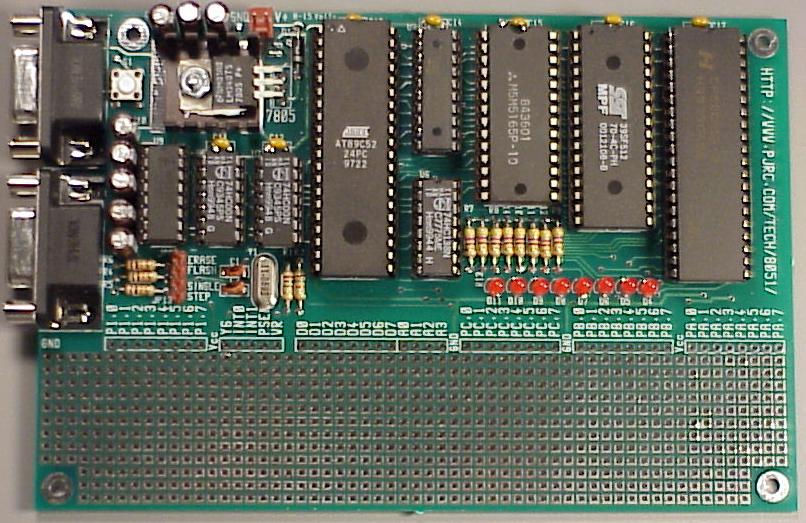
8051 Development Board: What It DoesThe 8051 development board provides an easy-to-use and low-cost way to develop your 8051 based microcontroller projects, without purchasing any other equipment, such as IC programmers or emulators. See below for a detailed list of the boards features.Close-Up View of the Development Board
FeaturesThe 8051 development board provides a number of features that are designed to make the board easy to use, and yet keep the cost of getting started with an 8051 based project as low as possible. Using a pre-programmed 87C52 chip, no other equipment (other than an unregulated power supply and serial cable) is required to develop projects based on the 8051 microcontroller. No expensive EPROM programmers or emulators are needed.PAULMON2 MonitorThe board uses PAULMON2 to provides a simple menu-based system that enables you to download your own code on the board. Unlike many other 8051 monitor programs, PAULMON2 has easy to understand menus, prompts, and most functions use a sequence of single keystroak commands. All functions have plenty of on-screen feedback, which makes learning the system quick and easy. PAULMON2 provides many features aside from program download, such as a full-screen memory editor, disassembler, and a simple single-step execution mode.A strong advantage of PAULMON2 is that the source code is available for free. You may use code from PAULMON2 in your project, without any restrictions. Because you have complete access to the code, there are no hidden secrets, and you can use its code and techniques in your own programs. If you are curious how it works, all of the code is available for you. You don't have to buy the board, PAULMON2 is available for free download from this page. The assembler that builds it, AS31, is also available for free, including source code. Flash ROM, Permanent User Program StorageAs you work on your project, most code downloads will be to the SRAM memory. When the your code is working, you will probably want to operate your project without needing it to be connected to your PC computer.The board contains a Flash ROM chip, which can hold your code permanently. Using PAULMON2, you can download code to the Flash ROM in almost exactly the same way as the SRAM (most, but not all, flash chips are able to write at 57600 baud, so you may need to use 19200 baud). PAULMON2 recognizes a 64 byte header, which you place into your program. Setting a few bytes in this header tells PAULMON2 to run your program when the board is booted, instead of running the normal menus. Example code is provided to bypass PAULMON2's automatic baud rate detection (requires Enter to be pressed at start up), so the board will be pre-configured to your desired baud rate, and then run your project's code. By using this non-volatile Flash ROM feature of the board and PAULMON2, you can easily make the board run your project when it is powered up. No EPROM or other device programmer is needed, and the difficult problems than can sometimes arise when a project is moved from a monitor environment to a complete stand-alone operation are easily avoided. If your code must be changed, or the board needs to be used for a different project, there is a jumper that will cause PAULMON2 to erase the Flash ROM when the board is rebooted, making the menu system available again for more development. It is also possible to use the Flash ROM for data logging projects, with some care. The flash programming routines within PAULMON2 may be called from your code, so that it is possible to write to the Flash ROM, even from a program that is executing from the flash memory. The Flash ROM supplied by PJRC.COM may be erased in 8k blocks. I/O Expansion, 32 Signals and 8 Bit Bus LinesThe board has an 82C55 chip, which provides 24 I/O lines, in addition to the 8 I/O pins from the 87C52's port 1. Eight of the 24 lines from the 82C55 have LEDs connected to them. The commonly used bus signals for I/O chips are also provided on the edge of the board, with clearly labeled silk screen lettering next to each pad.Serial Port SwitchingFor some projects, where the project communicates with another device, the menu system and code downloads could interfere with the other device which would "hear" all of this communication when the board is running PAULMON2 and not the project code. For these types of applications, the board has a second serial connector, and a simple switching circuit (controlled by pin 14 on the 87C52).To use this, the first action taken by the downloaded program would be to drive pin 14 low, causing the 8051's UART to be routed to the other DB-9 connector. While debugging, you code can temporarily switch the port back to send debugging messages to the PC screen. When the board is rebooted, the 87C52 drives this pin high automatically, so PAULMON2 will always reappear.... unless of course, there is a auto-startup program stored in the Flash ROM. Pad-Per-Hole Prototype AreaThe lower third of the board is a pad-per-hole prototype area, which provides enough space to construct the additional circuitry for many types of projects.Unregulated and Reverse Protected Input PowerThe board requires a single unregulated DC voltage, between 8 to 15 volts DC. A diode provides protection against reverse polarity power. A 7805 linear voltage regulator creates the five volts necessary to run all the parts on the board. The board contains a large copper fill area under the regulator, which provides adaquete heatsinking if standard CMOS components are used. All assembled boards and unassembled kits from PJRC.COM are provided with an heatsink component (as shown), to allow for additional power consumption by circuits to be added in the prototype area. |