Pulsed Output: PWM & Tone
Teensy can output pulses digital signals that are useful for many projects.Pulse Width Modulation
PWM creates an output with analog-like properties, where you can control the intensity in fine steps, even though the signal is really a digital pin rapidly pulsing.
| Board | PWM Capable Pins |
|---|---|
| Teensy 4.1 | 0, 1, 2, 3, 4, 5, 6, 7, 8, 9, 10, 11, 12, 13, 14, 15, 18, 19, 22, 23, 24, 25, 28, 29, 33, 36, 37, 42, 43, 44, 45, 46, 47, 51, 54 |
| Teensy 4.0 | 0, 1, 2, 3, 4, 5, 6, 7, 8, 9, 10, 11, 12, 13, 14, 15, 18, 19, 22, 23, 24, 25, 28, 29, 33, 34, 35, 36, 37, 38, 39 |
| Teensy 3.6 | 2, 3, 4, 5, 6, 7, 8, 9, 10, 14, 16, 17, 20, 21, 22, 23, 29, 30, 35, 36, 37, 38 |
| Teensy 3.5 | 2, 3, 4, 5, 6, 7, 8, 9, 10, 14, 20, 21, 22, 23, 29, 30, 35, 36, 37, 38 |
| Teensy 3.2 & 3.1 | 3, 4, 5, 6, 9, 10, 20, 21, 22, 23, 25, 32 |
| Teensy LC | 3, 4, 6, 9, 10, 16, 17, 20, 22, 23 |
| Teensy 3.0 | 3, 4, 5, 6, 9, 10, 20, 21, 22, 23 |
| Teensy++ 2.0 | 0, 1, 14, 15, 16, 24, 25, 26, 27 |
| Teensy 2.0 | 4, 5, 9, 10, 12, 14, 15 |
PWM is controlled with the analogWrite(pin, value) function.
  analogWrite(3, 50);
  analogWrite(5, 140);
Here are the actual waveforms this code creates on pins 3 and 5:
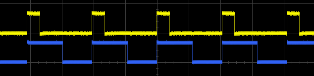 PWM Waveforms, values 50 and 140 |
The value is between 0 to 256, where the higher the value, the more time the signal remains high. Values 1 to 255 pulse the pin, referred to in perentage terms as "duty cycle". A value of 128 is 50% duty cycle.
Vales 0 and 256 are meant to correspond to logic low and high. However, the PWM hardware may not be capable of truly 100% low or high. A very short pulse may occur between each PWM cycle where the pin is driven to begin a new cycle, and then very quickly changed because the setting attempts to keep the pin always low or always high. To avoid any small glitch pulses, the pin may taken out of PWM mode using pinMode() and then controlled by digitalWrite().
PWM for LED Brightness
PWM is useful for controlling the brightness of LEDs. In this photo, 3 of the LEDs are driven by different PWM signals.
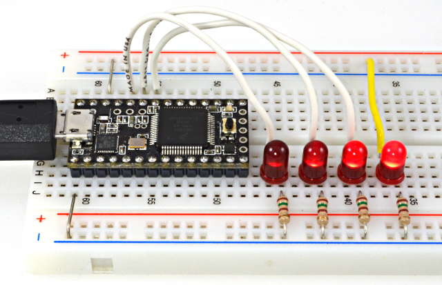 LED Dimming, with PWM values 10, 50, and 120 |
These LEDs are actually blinking very rapidly. Because the blinking happens much faster than the human eye can perceive, and much faster than the camera's shutter time for this photo, the result looks like a LED that is partially illuminated.
Most LEDs decrease in efficieny as you approach their maximum output. The human eye is less sensitive to differences between brightly lit objects. As you can see in the photo above, these 2 factors cause the LED with PWM value 120 to appear almost as bright as the right-most LED connected directly to the power. The PWM-driven LED really is using only 47% of the power.
When creating animated LED fading, consider changing the PWM value in larger steps when the value is larger, to achieve a more natural-looking result.
PWM for Motors
Pulse Width Modulation for controlling DC motors. The Teensy pins can not directly power a motor, so a transistor is used.TODO: photo: teensy3, motor, transistor, etc
TODO: schematic diagram, NPN transistor, arrows showing charge and discharge currents
TODO: talk about average current, charge and discharge paths and current ramps
Filtering PWM for Analog Output
PWM waveforms can turned into analog signals with a low pass filter. The simplest filter uses only a resistor and capacitor, for a very simple and low cost way to obtain an analog signal.
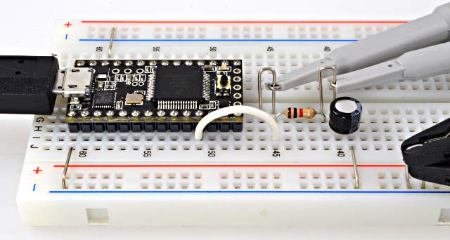 Filtering PWM with a Resistor and Capacitor |
Analog signals from PWM have caveats. If the power supply voltage changes or has noise, perhaps due to other devices that greatly vary in their power usage, the PWM high voltage varies, which in turn becomes a change to the filtered analog output.
Choosing the filter involves a trade-off between response speed and removing the PWM frequency. The lower the filter's corner frequency, the more steady the output becomes, but the slower it changes when you use analogWrite(). A more sophisticated filter can offer faster response and cleaner output, but at the cost of more components and complexity.
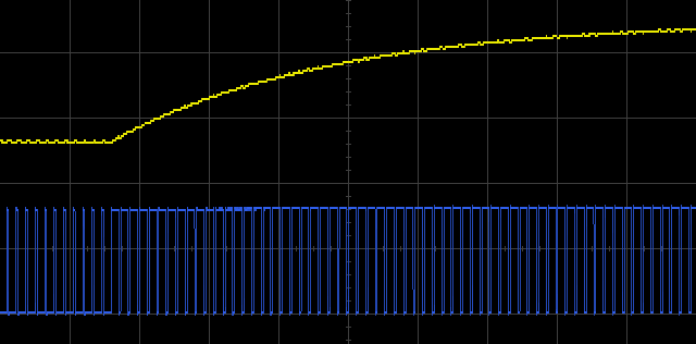
In the tests below, this code was used to create a PWM output which changes between 20% to 78% duty cycle.
void loop() {
  analogWrite(9, 50);
  delay(250);
  analogWrite(9, 200);
  delay(250);
}
Using a 1K resistor and 10µF capacitor gives a filter which leaves a substantial amount of the PWM frequency, but the output responds quickly when the PWM value changes.
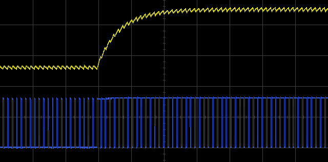 PWM Filtered by 1K Resistor & 10µF Capacitor |
Increasing the capacitor to 47µF results in a much smoother output, but the response is 5 times slower. Even this output has some of the PWM frequency present, so an even slower response would be needed to reduce it further.
 PWM Filtered by 1K Resistor & 47µF Capacitor |
A more complex filter can give faster response and smoother output, but such filters usually require opamp chips and many parts.
Another approach to smoother output is to increase the PWM frequency, so the filter can more easily remove it.
PWM Frequency
The PWM signals are created by hardware timers. PWM pins common to each timer always have the same frequency, so if you change one pin's PWM frequency, all other pins for the same timer change.
| Board | Timer | PWM Pins | Default Frequency |
|---|---|---|---|
| Teensy 4.1 | FlexPWM1.0 | 1, 44, 45 | 4.482 kHz |
| FlexPWM1.1 | 0, 42, 43 | 4.482 kHz | |
| FlexPWM1.2 | 24, 46, 47 | 4.482 kHz | |
| FlexPWM1.3 | 7, 8, 25 | 4.482 kHz | |
| FlexPWM2.0 | 4, 33 | 4.482 kHz | |
| FlexPWM2.1 | 5 | 4.482 kHz | |
| FlexPWM2.2 | 6, 9 | 4.482 kHz | |
| FlexPWM2.3 | 36, 37 | 4.482 kHz | |
| FlexPWM3.0 | 54 | 4.482 kHz | |
| FlexPWM3.1 | 28, 29 | 4.482 kHz | |
| FlexPWM3.3 | 51 | 4.482 kHz | |
| FlexPWM4.0 | 22 | 4.482 kHz | |
| FlexPWM4.1 | 23 | 4.482 kHz | |
| FlexPWM4.2 | 2, 3 | 4.482 kHz | |
| QuadTimer1.0 | 10 | 3.611 kHz | |
| QuadTimer1.1 | 12 | 3.611 kHz | |
| QuadTimer1.2 | 11 | 3.611 kHz | |
| QuadTimer2.0 | 13 | 3.611 kHz | |
| QuadTimer3.0 | 19 | 3.611 kHz | |
| QuadTimer3.1 | 18 | 3.611 kHz | |
| QuadTimer3.2 | 14 | 3.611 kHz | |
| QuadTimer3.3 | 15 | 3.611 kHz | |
| Teensy 4.0 | FlexPWM1.0 | 1, 36, 37 | 4.482 kHz |
| FlexPWM1.1 | 0, 34, 35 | 4.482 kHz | |
| FlexPWM1.2 | 24, 38, 39 | 4.482 kHz | |
| FlexPWM1.3 | 7, 8, 25 | 4.482 kHz | |
| FlexPWM2.0 | 4, 33 | 4.482 kHz | |
| FlexPWM2.1 | 5 | 4.482 kHz | |
| FlexPWM2.2 | 6, 9 | 4.482 kHz | |
| FlexPWM3.1 | 28, 29 | 4.482 kHz | |
| FlexPWM4.0 | 22 | 4.482 kHz | |
| FlexPWM4.1 | 23 | 4.482 kHz | |
| FlexPWM4.2 | 2, 3 | 4.482 kHz | |
| QuadTimer1.0 | 10 | 3.611 kHz | |
| QuadTimer1.1 | 12 | 3.611 kHz | |
| QuadTimer1.2 | 11 | 3.611 kHz | |
| QuadTimer2.0 | 13 | 3.611 kHz | |
| QuadTimer3.0 | 19 | 3.611 kHz | |
| QuadTimer3.1 | 18 | 3.611 kHz | |
| QuadTimer3.2 | 14 | 3.611 kHz | |
| QuadTimer3.3 | 15 | 3.611 kHz | |
| Teensy 3.6 | FTM0 | 5, 6, 9, 10, 20, 21, 22, 23 | 488.28 Hz |
| FTM1 | 3, 4 | 488.28 Hz | |
| FTM2 | 29, 30 | 488.28 Hz | |
| FTM3 | 2, 7, 8, 14, 35, 36, 37, 38 | 488.28 Hz | |
| TPM1 | 16, 17 | 488.28 Hz | |
| Teensy 3.5 | FTM0 | 5, 6, 9, 10, 20, 21, 22, 23 | 488.28 Hz |
| FTM1 | 3, 4 | 488.28 Hz | |
| FTM2 | 29, 30 | 488.28 Hz | |
| FTM3 | 2, 7, 8, 14, 35, 36, 37, 38 | 488.28 Hz | |
| Teensy 3.2 Teensy 3.1 | FTM0 | 5, 6, 9, 10, 20, 21, 22, 23 | 488.28 Hz |
| FTM1 | 3, 4 | 488.28 Hz | |
| FTM2 | 25, 32 | 488.28 Hz | |
| Teensy LC | FTM0 | 6, 9, 10, 20, 22, 23 | 488.28 Hz |
| FTM1 | 16, 17 | 488.28 Hz | |
| FTM2 | 3, 4 | 488.28 Hz | |
| Teensy 3.0 | FTM0 | 5, 6, 9, 10, 20, 21, 22, 23 | 488.28 Hz |
| FTM1 | 3, 4 | 488.28 Hz | |
| Teensy 2.0 | 0 | 5 | 976.56 Hz |
| 1 | 4, 14, 15 | 3921.57 Hz | |
| 3 | 9 | 3921.57 Hz | |
| 4 | 10, 12 | 3921.57 Hz | |
| Teensy++ 2.0 | 0 | 0 | 976.56 Hz |
| 1 | 25, 26, 27 | 3921.57 Hz | |
| 2 | 1, 24 | 3921.57 Hz | |
| 3 | 14, 15, 16 | 3921.57 Hz |
Teensy LC, 3.x, 4.x support the analogWriteFrequency(pin, frequency) function to easily configure the PWM.
    void setup() {
      analogWriteFrequency(4, 375000); // Teensy 3.0 pin 3 also changes to 375 kHz
    }
The analogWriteFrequency function has a lower limit of a few Hz. See this conversation for code to reach extremely slow speeds.
On all Teensy 3.x boards, the FrequencyTimer2 library may be used to obtain a different frequency (than the FTM0 timer) on pin 5 using the CMT timer.
For Teensy 2.0 and Teensy++ 2.0, the TimerOne & TimerThree libraries can be used to control the PWM frequency.
PWM Resolution (Teensy LC, 3.0 - 3.6, 4.0, 4.1)
Normally analogWrite(pin, value) is used with the value between 0 to 255, which corresponds to 8 bit resolution. Writing 256 forces the pin always high. Teensy LC &x:w, 3.x support an analogWriteResolution(bits) function, to reconfigure analogWrite.
    void setup() {
      analogWriteResolution(12);  // analogWrite value 0 to 4095, or 4096 for high
    }
This function only configures the analogWrite value range, which is mapped to the hardware's capability. The actual resolution available depends on the PWM frequency, where slower frequencies have higher resolution.
For example, if you set the PWM frequency to 375 kHz and the resolution to 10 bits, analogWrite will automatically map the 0-1023 values to the available 0-127 range. Your code can write values from 0 to 1023, but groups of 8 consecutive values will produce the same output.
To configure both frequency and resolution for matching performance, use the values from this table:
| Board | Resolution (# of bits) | PWM Value | Ideal Frequency CPU Speed: 600, 450 MHz | Ideal Frequency CPU Speed: 528, 396 MHz | Ideal Frequency CPU Speed: 24 MHz |
|---|---|---|---|---|---|
| Teensy 4.1 Teensy 4.0 FlexPWM Timers | 15 | 0 - 32757 | 4577.64 Hz | 4028.32 Hz | 732.422 Hz |
| 14 | 0 - 16383 | 9155.27 Hz | 8056.64 Hz | 1464.84 Hz | |
| 13 | 0 - 8191 | 18310.55 Hz | 16113.28 Hz | 2929.69 Hz | |
| 12 | 0 - 4095 | 36621.09 Hz | 32226.56 Hz | 5859.38 Hz | |
| 11 | 0 - 2047 | 73242.19 Hz | 64453.13 Hz | 11718.75 Hz | |
| 10 | 0 - 1023 | 146484.38 Hz | 128906.25 Hz | 23437.5 Hz | |
| 9 | 0 - 511 | 292968.75 Hz | 257812.5 Hz | 46875 Hz | |
| 8 | 0 - 255 | 585937.5 Hz | 515625 Hz | 93750 Hz | |
| 7 | 0 - 127 | 1171875 Hz | 1031250 Hz | 187500 Hz | |
| 6 | 0 - 63 | 2343750 Hz | 2062500 Hz | 375000 Hz | |
| 5 | 0 - 31 | 4687500 Hz | 4125000 Hz | 750000 Hz | |
| 4 | 0 - 15 | 9375000 Hz | 8250000 Hz | 1500000 Hz | |
| 3 | 0 - 7 | 18750000 Hz | 16500000 Hz | 3000000 Hz | |
| 2 | 0 - 3 | 37500000 Hz | 33000000 Hz | 6000000 Hz |
On Teensy 4.x, by adjusting the CPU frequency you can create other precise PWM frequencies.
| Board | Resolution (# of bits) | PWM Value | Ideal Frequency CPU Speed: 180 or 120 MHz | Ideal Frequency CPU Speed: 48 or 96 MHz | Ideal Frequency CPU Speed: 72 MHz | Ideal Frequency CPU Speed: 24 MHz |
|---|---|---|---|---|---|---|
| Teensy 3.6 except pins 16-17 Teensy 3.5 Teensy 3.2 Teensy 3.1 Teensy 3.0 | 16 | 0 - 65535 | 915.527 Hz | 732.4218 Hz | 549.3164 Hz | 366.2109 Hz |
| 15 | 0 - 32767 | 1831.055 Hz | 1464.843 Hz | 1098.632 Hz | 732.421 Hz | |
| 14 | 0 - 16383 | 3662.109 Hz | 2929.687 Hz | 2197.265 Hz | 1464.843 Hz | |
| 13 | 0 - 8191 | 7324.219 Hz | 5859.375 Hz | 4394.531 Hz | 2929.687 Hz | |
| 12 | 0 - 4095 | 14648.437 Hz | 11718.75 Hz | 8789.062 Hz | 5859.375 Hz | |
| 11 | 0 - 2047 | 29296.875 Hz | 23437.5 Hz | 17578.12 Hz | 11718.75 Hz | |
| 10 | 0 - 1023 | 58593.75 Hz | 46875 Hz | 35156.25 Hz | 23437.5 Hz | |
| 9 | 0 - 511 | 117187.5 Hz | 93750 Hz | 70312.5 Hz | 46875 Hz | |
| 8 | 0 - 255 | 234375 Hz | 187500 Hz | 140625 Hz | 93750 Hz | |
| 7 | 0 - 127 | 468750 Hz | 375000 Hz | 281250 Hz | 187500 Hz | |
| 6 | 0 - 63 | 937500 Hz | 750000 Hz | 562500 Hz | 375000 Hz | |
| 5 | 0 - 31 | 1875000 Hz | 1500000 Hz | 1125000 Hz | 750000 Hz | |
| 4 | 0 - 15 | 3750000 Hz | 3000000 Hz | 2250000 Hz | 1500000 Hz | |
| 3 | 0 - 7 | 7500000 Hz | 6000000 Hz | 4500000 Hz | 3000000 Hz | |
| 2 | 0 - 3 | 15000000 Hz | 12000000 Hz | 9000000 Hz | 6000000 Hz | |
| Teensy LC | 16 | 0 - 65535 | - | 732.4218 Hz | - | 732.4218 Hz |
| 15 | 0 - 32767 | - | 1464.843 Hz | - | 1464.843 Hz | |
| 14 | 0 - 16383 | - | 2929.687 Hz | - | 2929.687 Hz | |
| 13 | 0 - 8191 | - | 5859.375 Hz | - | 5859.375 Hz | |
| 12 | 0 - 4095 | - | 11718.75 Hz | - | 11718.75 Hz | |
| 11 | 0 - 2047 | - | 23437.5 Hz | - | 23437.5 Hz | |
| 10 | 0 - 1023 | - | 46875 Hz | - | 46875 Hz | |
| 9 | 0 - 511 | - | 93750 Hz | - | 93750 Hz | |
| 8 | 0 - 255 | - | 187500 Hz | - | 187500 Hz | |
| 7 | 0 - 127 | - | 375000 Hz | - | 375000 Hz | |
| 6 | 0 - 63 | - | 750000 Hz | - | 750000 Hz | |
| 5 | 0 - 31 | - | 1500000 Hz | - | 1500000 Hz | |
| 4 | 0 - 15 | - | 3000000 Hz | - | 3000000 Hz | |
| 3 | 0 - 7 | - | 6000000 Hz | - | 6000000 Hz | |
| 2 | 0 - 3 | - | 12000000 Hz | - | 12000000 Hz |
Teensyduino 1.23 and later accept a floating point number with analogWriteFrequency(), so you can set precise low frequencies for optimized PWM resolution.
On Teensy LC, the timers operate directly from the main clock generator, so the ideal frequency and PWM resolution do not scale with CPU clock speed, as on Teensy 3.0 - 3.6.
On Teensy 3.6, pins 16 & 17 operate from a fixed 16 MHz clock. For these pins, the ideal frequency is one third of the ideal PWM frequency at 48 MHz.
Tone
The tone() function is useful for simple audio. It outputs a square wave at the frequency you specify. There are generally 2 ways to use tone:
    tone(pin, frequency);       // Begin the tone
    delay(300);
    noTone(pin);                // manually stop it

    tone(pin, frequency, 300);  // Begin a tone which automatically stops
Either way, the tone() function returns quickly and your code continues to run while the pin outputs the specified frequency. An example can be opened from File > Examples > 02.Digital > toneMelody.
When playing a sequence of tones, sometimes it is easier to start and stop the tone. For other uses, especially output of a beep for user feedback, the automatic stop is very convenient.
To connect a speaker, a 330 ohm resistor and 100 µF capacitor are recommended. The negative terminal of the capacitor connects to the speaker.
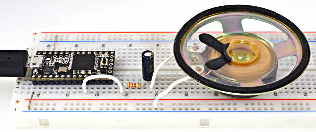 Speaker with tone(), using 330 Ohm Resistor & 100µF Capacitor |
Teensy 2.0 has a known issue where tone() will not play if you call the tone() function repetitively at high speed, restarting the tone over and over before it can begin. A future version of Teensyduino will correct this issue. As a workaround, do not call tone() again while the previous tone is still playing.
Tone uses a timer interrupt. If libraries that use interrupts create excessive interrupt latency, tone's pulsing can be delayed, creating an incorrect frequency. SoftwareSerial and OneWire are libraries known to potentially interfere with tone().