Blog Posts

RCA 118 “tombstone” MP3 Player

Mike Mitchell (dundakitty of the forum) took an old RCA 118 radio and turned into a very classy looking MP3 player.

The radio was stripped down to it’s chassis, retaining the original tuning dial and the knobs.  A couple of small speakers and a 20-watt stereo amplifier that are both controlled by a Teensy 3.6.

MP3 files of old radio broadcasts were collected and loaded onto a micro SD card.  The Teensy reads the capacitance of the tuner to randomly select a directory and file on the SD card to play.   The Teensy Audio Library was used to add a “hissing” sound between stations for an authentic old-time radio effect.  The project is housed in a beautiful, custom-made cabinet.


Larry’s Coffee Roaster

Larry McGovern (elkayem) developed a very cool coffee roaster that can roast up to a half pound of coffee using a custom roasting profile.

This fluid-bed style roaster can run in one of two modes – auto, where the temperature and fan speed are controlled by a settable profile; or manual, where the temperature and fan speed can be controlled in real time.    Temperatures, set value, fan speed, and heater duty cycle measurements are saved to an SD card while roasting as a CSV file for later analysis.

The roaster also has the ability to interface with Artisan Roaster Scope, an open-source software program for coffee roasting that records, analyzes, and controls roast profiles.  While the Teensy 3.5 used in the project collects roast data to the SD card, Artisan includes some nice features to analyze your roast.

There is a great detailed write up on this Git Hub page.  It not only includes code for the project, but schematics, Eagle files, files for the 3D printing of a few parts, and files to laser cut the the case.

Teensyboy by Catskull Electronics

David DeGraw of Catskull Electronics has developed Teensyboy, an awesome little MIDI adapter for a Nintendo Gameboy.

This compact little shield is about the size of thumb drive and uses USB MIDI.  Simply plug it into into a computer and fire up your favorite digital audio workstation (DAW) and you’ll be jamming with your Gameboy before you know it.

There is also a Teensyboy Pro that includes a variety of modes to accommodate Little Sound DJ (LSDJ), Nanoloop and mGB.  It also has convenient mounting holes for installation into a case.

Vague Robots has some tutorial videos on using the Teensyboy Pro with LSDJ

The software is available on catskull’s gitHub repository.  It’s a fork of this Arduinoboy software by trash80.

Countdown To 100th Birthday

Max created this beautiful countdown timer to his 100th birthday.

Max used Lixie displays, a ChronoDot for high accuracy time keeping, and a Teensy 3.6 to control everything, inside a beautifully stain finished wooden cabinet with brass trim.

Check out Max’s many excellent articles, working with the Lixie displays, mounting with brass hardware, and assembling the enclosure for a detailed log of the building process.  Max also published the complete source code, and let us know about his project by this forum thread.

Improving Arduino Serial Monitor Performance

Recently I’ve been working to improve the Arduino Serial Monitor.  Here it is running with Teensyduino 1.48-beta1.

Previously if a board sent data this fast (as Teensy 4.0 can), Java would run out of memory and the Arduino IDE crashes.

Teensy 4.0’s USB code is not yet fully optimized, so we can expect even greater speeds later this year.  The Arduino Serial Monitor needs improvement to handle these faster data rates!

Deja Vu From 2014

This isn’t the first time Teensy has crashed Arduino by sending too rapidly to the Serial Monitor.  Back in 2014, this same problem existed with Teensy 3.1.  Serial.print() without delay on Teensy 3.1 would cause Java to run out of memory and crash the Arduino IDE.

Arduino Due was also capable of crashing the Arduino IDE this way.  The Arduino developers had tried in October 2014 to solve it by limiting the buffered data size, which helped, but still Java would eventually run out of memory and lock up.

On December 6, 2014, I finally managed to work around the problem well enough for Arduino to handle sustained USB full speed (12 Mbit/sec) incoming data.  My solution worked around the terrible slowness of adding and removing data from the JTextArea component by collecting incoming data to a buffer and using a timer to add data at only 30 Hz rate.  It also limited the rate of removal to only once every 150 adds, and removed by the number of characters rather than the number of lines.  4 days later, the Arduino developers adapted my solution and merged it into Arduino.  This code as been in every version of Arduino since 1.6.0.

At the time, I wrote this explanation of the details and rant about Java performance.  Back then I wrote “Java is pretty horrible”.  Now with the benefit of hindsight, I realize I was equating Swing’s JTextArea and JTextComponent classes (and the complicated data storage infrastructure lurking behind them) with Java in general.  I also wrote “if dramatically faster hardware is made … in the future, this buffer might need to grow”.

Now with Teensy 4.0 bringing that dramatically faster hardware, and some hindsight, I’ve learned how so much more than merely increasing the size of an intermediate buffer is needed to support sustained data transfer at such speed.

What’s Really Using So Much Memory?

I quickly discovered the terrible slowness inside JTextArea & JTextComponent scaled up (or “down”) rapidly with data size.  Keeping the same 30 updates per second but with larger data would not work.  It failed spectacularly.  Under the load of Teensy 4.0 printing without delay, the Arduino IDE would run slowly for a matter of seconds, then on Windows and Mac start throwing OutOfMemoryError exceptions and ultimately lock up.  On Linux, it would keep running, but unusably slow and consume many gigabytes of memory.  Not good.

To start digging into the problem, I ran VisualVM, which is a Java profiler.  It’s one of the programs bundled with the Java SDK.  If you have the SDK and a JAVA_HOME environment variable (the usual setup for compiling Arduino from source), it can be run from the command line with “$JAVA_HOME/bin/jvisualvm”.

VisualVM is very easy to use.  Every Java-based program running on your machine shows up in the “Local” group.  Arduino appears as “processing.app.Base (pid [number])”.  Clicking it connects the profiler to the running Arduino IDE.  Then clicking the “Profiler” tab lets you see which Java classes are using so much memory.

This screenshot shows the memory use after only several seconds of Teensy 4.0 printing rapidly to the Serial Monitor.  While 100 megabytes is used by raw character data, the really startling result is nearly 2 million live instances of GapContent$MarkData, GapContent$UnfoPosRef, AbstractDocument$LeafElement, and GapContent$StickyPosition.  Yikes!

Even on Linux, with the extra burden of the VisualVM profiler, Java quickly crashes under the strain of Teensy 4.0 printing without delays.  But the profiler served its purpose, so shine light on what’s consuming such an insane amount of memory.  GapContent appeared to the culprit.

Flexible or Bloated, A Matter of Perspective?

Java has a pretty amazing amount of good documentation.  Google searches always turn up Oracle’s reference material.  Usually searches turn up many nice Java tutorials and well answered questions on sites like Stack Overflow.  But from the lack of non-reference material, not even unanswered questions (other than people trying to use JTextArea or JTextComponent as a terminal or live log file display and hitting these same memory use problems), it seems this part of Java is a seldom traveled path.  That’s much of the reason I’m taking some time to write this lengthy blog article, to share with you what I’ve learned on this optimization journey.

I spent a lot of time reading the Java reference pages.  A lot of time…

Internally a number of Java classes are used in a rather modular way.  This modularity could be been seen a highly flexibly or highly bloated system, either a blessing or a curse, depending on your perspective.  In the end, the modular nature turned out to be quite useful.  But first, let’s look at how it’s structured.

This diagram from the JTextComponent reference best sums up the way things really work under the hood.

If you compare with Oracle’s page, you’ll see I’ve add the GapContent part to this diagram.  It turns out the Document class actually outsources all the data storage to GapContent.  At one point I had imagined just replacing GapContext with something more efficient.  But sadly, the GapContent API is designed around the assumption that the data size grows to any arbitrary size.  I wanted to replace all the storage with a fixed-size FIFO circular buffer and avoid *any* use dynamically allocating classes or large data on the heap during the sustained processing of data.

FifoDocument Class

GapContent had to go, so I started work on a new FifoDocument class which would hold all the Serial Monitor text in a fixed size array.

The idea was simple.  Since we only new add lines at the end, and delete the oldest lines from the beginning, this ought to be simple, right?

Elements & Events

At first I did not understand the purpose of the Element class.  I imagined just sending a DocumentEvent output with a single Element representing all the text.  If you read only that Element reference, perhaps you can see how it seems to imply that might work?  At least that’s what I incorrectly assumed.

The Document reference is the only other page (which I found) describing Elements.  But it only describes how they might be used in a generic way.  This Element structure image is completely wrong for the use case of JTextComponent.

It turns out JTextComponent expects a single top-level Element as a container for the entire document, which has child Elements representing each line.  Near the end of the explanation on that Document reference page is a dead link to “see The Swing Connection and most particularly the article, The Element Interface“.  Every indication is Oracle deleted “The Swing Connection” blog many years ago, and dead links automatically redirect to the generic Java page.

Fortunately I did find a copy of The Element Interface article archived at an academic site.  This article is essential to understand what Element structure the various Java Document classes actually use, if you want to craft your own custom Document class to replace on of them.  For the Arduino Serial Monitor case, it’s the PlainDocument structure.

My initial hope to use a single Element was replaced by adding a large, fixed size array of FifoElementLine instances which keep track of where the individual lines of data are located within the big FIFO circular buffer.

With this addition and many trial-and-error tests to figure out which functions actually get called, *finally* the Serial Monitor window started responding to the DocumentEvent notifications and displayed the text.

An early experiment also showed that FifoDocument could delete data without receiving any input from JTextArea.  By simply sending an event to notify JTextArea that data has been deleted, indeed the Serial Monitor would update properly.  This highly flexible event-based design that could be seen as bloat turned out to be very useful for implementing an efficient FIFO that automatically discards old data.

Later this ability for the Document to notify the GUI of changes (which it didn’t initiate or participate in any way) turned out to be even more useful for directly adding data into the FIFO.

Bugs & Thread Safety

Without the help of several great people on the PJRC Forum, especially Tim (Defragster), FifoDocment probably never would have reached a usable state.  The DocumentEvent interface involves many complex requirements which are only scantly documented.  Many tries were needed to get everything right.  Defragster found pretty much every bug very quickly.

Even after the “easy” bugs where fixed, thorny problems with threads remained.  I ended up making almost all the public methods of FifoDocument synchronized.  The thread which adds new data into FifoDocument is also called using SwingUtilities.invokeAndWait().  These are less than optimal.  Perhaps later even better performance could be possible?

Direct Write Into FIFO Memory

Even with all these optimizations, Java would still run out of memory on some Macintosh machines.  Arduino’s traditional implementation of the serial monitor makes multiple copies of incoming data before it finally ends up stored in FifoDocument (or GapContent).

First, the Serial class has an event handler which receives incoming characters into a buffer, which is allocates on the heap.  Then that buffer is converted to a String and passed to a message() function, which is the abstraction allowing different classes to receive data.  The contents of that String are then copied into a StringBuffer instance, which is the improvement I contributed 5 years ago.  At a rate of 30 Hz, then StringBuffer is then copied another String instances, which is passed to JTextArea, which then passes it to the Document storing the data.

I replaced all this copying of data with path directly from arriving characters into the FifoDocument character buffer.

Unfortunately this means overriding the usual path data takes between the abstract serial monitor classes.  Instead, a single loop waits for data to arrive.  When data is ready to read, it requests the maximum number of bytes FifoDocument can accept, and the offset where that data goes inside FifoDocument’s fixed size buffer.  It then reads incoming characters directly from the input stream to FifoDocument’s buffer.  No extra copies are made in other buffers, or String instances to pass the data between abstraction layers.

With this final optimization, even older Macs could continuously receive from Teensy 4.0 without running out of memory or locking up.

However, Java’s InputStreamReader class is still used to convert the raw bytes from UTF8 format to Java’s internal handling of all characters, and the Document event API still uses heap-based temporary allocations for some features.  These do still cause Java’s memory usage to grow gradually, then suddenly shrink what Java’s garbage collection runs.  But at least initial testing appears as if this overhead is acceptable.

Auto Scroll Behavior

While developing the FifoDocument with a truly fixed size buffer, I was forced to make some hard decisions about how to handle the Serial Monitor’s auto-scroll checkbox.

Since Arduino 1.6.0, the Serial Monitor has used a target size of 4,000,000 characters for its buffer (half of the maxChars size in the TextAreaFIFO class).  But this only checked every 150 updates, which can happen no faster than 30 Hz.  Regardless of the auto-scroll checkbox, if the stored data has grown longer than 4,000,000 characters, the oldest data is deleted so only 4,000,000 characters remain.

FifoDocument has a fixed size buffer, rather than the flexible storage of GapContent, so I was not able to preserve this functionality.  I’m also not convinced this existing approach is really correct, since rapidly arriving data can cause whatever the user is trying to read to be deleted.  The TextAreaFIFO class as a flag to tell whether to trim the oldest data, but in all modern versions of Arduino it is never used or changed.

For FifoDocument, I implemented a buffer management policy where the buffer is allowed to fill to 60% capacity while scrolling.  During sustained scrolling, 40% of the buffer remains free.

When auto-scroll is disabled, FifoDocument allows new data to completely fill the buffer.  Once the buffer is 100% full, FifoDocument discards new data.  This may be a controversial decision.  The idea is to allow the user to read anything already within the buffer, and everything new which arrives until the buffer becomes 100% full.  The Serial Monitor window can’t jump to go blank if too much new data pours in while the user is reading.  But once the fixed size buffer is full, nothing more can be captured until auto-scroll is turned back on.

FifoDocument currently implements a 10,000,000 character buffer, and a maximum of 1,000,000 lines.  This allows more data to be captured, but the behavior is not exactly the same as current versions of Arduino when auto-scroll is turned off.

Performance

Despite my frustrated words 5 years ago, indeed Java is capable of implementing the serial monitor at these higher speeds.  But the pervasive approach of most Java code, allocating new objects while passing data between many abstraction layers, puts far too much burden on Java’s memory management and garbage collection.  Using a fixed size buffer, with incoming data stored directly to the buffer without allocating copies on Java’s heap is indeed fast enough.

In a somewhat surprising result, the most efficient system for this use is Microsoft Windows 10.

The Java virtual machine appears to run Java code more efficiently on Windows than it does on Macintosh and Linux.  Perhaps Oracle (or Sun) invested more work to optimize the JRE for Windows?

In this screenshot, you can see the “teensy_serialmon” program running, also with low CPU usage.  This helper program talks to Teensy using Windows native WIN32 functions and then passes the data to Java using stdin & stdout streams.  On Windows 10, both the built in serial driver and the lightweight anonymous pipes used for stdin/stdout appear to be very efficient when accessed with native WIN32 functions.

While Linux is not far behind Windows, unfortunately Macintosh appears to have considerable CPU overhead for accessing serial devices.

This screenshot was taken on the same Macbook Air as the Windows 10 test above (running natively, via Bootcamp dual boot).

However, the Macintosh USB drivers allow Teensy 4.0 to transmit about 60% faster than the drivers on Windows and Linux.  When running the USB serial print speed benchmark, Linux and Windows usually sustain about 200,000 lines/second.  Macintosh usually runs just over 300,0000 lines/second.

These differences are very likely an artifact caused by less-than-optimal USB driver code on Teensy 4.0, interacting with subtle timing differences in the USB host drivers on each system.  I have been delaying work for USB optimizations on Teensy 4.0 until the Serial Monitor is capable of handling the incoming speed without crashing the Arduino IDE.  Now, with these improvements, I can start to focus my effort on optimizing the Teensy side!

Arduino Contribution

As always, my intention is to contribute Teensy-inspired improvements to the Arduino IDE back to the Arduino project.  Several weeks ago I exchanged a few emails with the Arduino developers about this Serial Monitor optimization work, so they are aware of my effort.  Part of the reason to write this lengthy article is to document this work from a “high level” perspective which isn’t really possible by the comments in the code which give more detail.

All of this source code is published on Github.  These are the files:

  • FifoDocument.java – All the FIFO and Document code
  • TeensyPipeMonitor.java – Teensy’s “Pluggable” Serial Monitor using FifoDocument.  This file creates the listener threads which receive stdin data directly into FifoDocument’s buffer, and parse stderr for status updates.
  • FifoEvent.java – The event info FifoDocument sends to JTextComponent.  Methods just call the actual implementation in FifoDocument.
  • FifoElementLine.java – The Element instances representing individual lines of text.  Methods just call the actual implementation in FifoDocument.
  • FifoElementRoot.java – The top-level Element required by JTextComponent.
  • FifoPosition.java – The Position interface which JTextComponent requires for users to select text and copy to clipboard.  Positions are actually implemented with a 64 bit total-historic offset, as explained in this comment.

This work could be considered 2 separate contributions, even though their code is now pretty tightly integrated.  The other work could be called “Pluggable Serial Monitor”, similar in concept to Pluggable Discovery.  The concept, like with discovering ports, is a board can provide a program like “teensy_serialmon” which does the actual communication and makes it available to the Arduino IDE using stdin & stdout streams.  Teensy has used this approach in beta testing since early 2017, and released in Teensyduino 1.42  June 2018).  The port discovery portion was accepted by Arduino around that time.  The serial monitor part will hopefully become an official Arduino feature at some point in the future.

Whether this serial monitor performance improvement may ever accepted by Arduino is unclear.  Arduino has announced at Maker Faire and Arduino Day (March 2018) a next-gen Arduino IDE which will no longer use Java.  How they feel about merging such a large change to the existing Java code is unclear, especially when Teensy 4.0 is (probably) the only board available today which can transmit at these speeds which crash the existing IDE.

Still, my hope is this code may eventually find its way into an official Arduino release.  Eventually more microcontrollers will appear on the market with 480 Mbit or faster USB, and fast enough processors and USB code capable of sustained printing at these speeds and perhaps much faster.

When anyone is later interested in this Serial Monitor optimization, hopefully this lengthy article and the code on github will help.

Ferrofluid Display

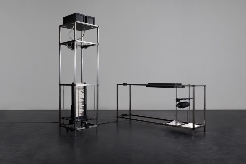
A group of student group at University of Oslo called Applied Procrastination created this amazing display using 252 electro magnets… and gravity.

Teensy 3.6 and optimized code allowed fast enough control to hold the fluid stable.

Detailed are published on this Hackster page, and also this Hackday.io writeup.   The complete source code is published on github.

Their impressive software work is built on top of hardware featuring pretty amazing craftsmanship.  A grid 252 electro-magnets provide the force to move and suspend the display’s black fluid.

Electromagnets don’t just run themselves.  The team had to create a dozen custom driver circuit boards to control all those individual magnetic fields.

Really impressive work from this team!


Kelpie – Portable MIDI Synth

Kenneth Marut designed and developed the KELPIE, a portable monphonic and polyphonic digital synthesizer.

This incredible little synth is a great way for beginners to get started in the world of synthesizers.  It only requires a power supply and a MIDI connection that can plug right into MIDI device such as a keyboard.  It also include a 1/4″ mono output and 1/8″ stereo output.   The workmanship and attention to detail on this project is impressive.

Kenneth rolled his own Teensy 3.2 and Audio Shield to create the KELPIE and used Teensy Audio Library.  It includes USB input so that you can update the code.

More details on the project can be found on this project page.

This project is open source with hardware files and code available on GitHub.

thingSoC Adapter for Teensy 3x

Pattern Agents have developed TSOC_Teensy3x, a thingSoC adapter that allows you to connect thingSoC, Mikrobus, and Grove System modules using a Teensy 3.2

This clever adapter can be used with any thingSoC, Mikrobus, or Grove System modules.  It also works with a number of different IoT comptaible wireless radio modules as well as many different input and output sensors and modules giving you a lot of flexibility with a variety of sensors and actuators.

Additional details on the project are available on GitHub.

Breakout Board for Teensy 4.0

During the Teensy 4.0 beta test we made these breakout boards, to easily test hardware features.  They were also sent to Hackaday, Hackster, and Hackspace Magazine for reviews.

Now we’re sharing all the info, so you can make your own copy of this breakout board!

Breakout Board Features

First, let’s look at the main features.

  1. Main USB for Teensy 4.0.  The entire board gets power from this USB connector, so it must be plugged in for the eval board to work.
  2. Second USB host port.  To test this, plug in a USB keyboard or MIDI keyboard or drum pad.  In Arduino, click File > Examples > USBHost_t36 > Test for a simple program which responds to events from those types of USB devices.  The eval board has a TPS2055A current limit chip, which allows most USB devices to be hot plugged while running from USB power provided over the main USB port.
  3. Audio shield output.  Plug in headphones or computer speakers.  Recommend running File > Examples > Audio > Synthesis > Guitar to test the audio output.
  4. SD card accessed by SPI with pin 10 for CS.  The eval kit comes with a 32 GB card pre-loaded with 4 public domain music files.  Recommend running File > Examples > Audio > WavFilePlayer for a first test.
  5. SD card accessed by SDIO (4 bit).  To test this, run any of the SD library examples.  Edit the chip select pin to BUILTIN_SDCARD.  An 8 pin flat flex cable connects between the Teensy 4.0 and peripheral board to provide access to the SDIO pins.
  6. Coin cell holder (CR2032 type battery), for RTC backup.  Run File > Examples > Time > TimeTeensy3 to access the RTC date/time.
  7. Power On/Off button.  Hold for 5 seconds to completely shut off 3.3V power.  Press for 1/2 second to turn back on.  If a coin cell is installed, the power on/off state will be retained when you disconnect the USB cable.  Without the coin cell to maintain power management state, the 3.3V power will default to “on” when power is applied.
  8. Power LED, to visually confirm if the 3.3V power is turned on.
  9. Serial1 to Serial7.  These 6 pin headers mate with the commonly available FTDI TTL-level cables, and numerous boards following that 6 pin format.  For a quick test program, click File > Examples > Teensy > Serial > EchoBoth.  If using Serial2 or higher, edit the define in that program.
  10. CAN FD port.  Use the FlexCAN_t4 library to access this port.  Unfortunately, the labels printed on the eval board are backwards.  On the original boards (shown in these photos), the center pin labeled “CANL” is actually “CANH”, and the right hand pin labeled “CANH” is actually “CANL”.  The shared PCB files have this error corrected.  If your CAN bus requires a termination, a 120 ohm resistor can be soldered to the eval board.
  11. Ground test point.  Handy if you wish to make measurements with a voltmeter or oscilloscope.  🙂

Circuit Board

The PCB is available as an OSH Park shared board.  You can buy it from OSH Park, or use the Download button on that page to get the PCB gerber files.

Connections to Teensy 4.0 Bottom Side

To connect to the bottom side of Teensy 4.0, the breakout board uses these spring-loaded pogo pins.  Either 12 to 12.5 mm height can be used for the pins which touch the flat surface mount pads.  12.5 works best to contact to the On/Off and VBAT pins.


These pogo pins were purchased from RTLECS.  (new RTLECS link)  RTLECS sells on Aliexpress, Ebay and maybe other sites.  If you have trouble finding them, the ones we used for the beta test came in this bag with contact info.

While there are 14 locations to solder these these pogo pins, Teensy pins 26, 27, 32, 33 are not routed on the breakout board.  You only need 10 pogo pins to fully utilize all the breakout board features.  Many of the ones built for the beta test had only 6 pogo pins, leaving off the 4 pins to for Serial6 & Serial7.

The 8 pins for native SD card support are connected by a FFC (flat flex cable) between Teensy 4.0 and the breakout board.

Credit to Defragster for sharing this photo on the forum.  Also in this photo you can see one of the earlier beta test boards, which had a white wire soldered to the bottom to correct a brown-out restart problem discovered during beta testing.  The final Teensy 4.0 boards have this wire routed on layer 3 (of 6) inside the PCB.

Parts List

Here is a complete list of parts needed to fully build the breakout board.  Some of these parts may be left off if you do not need all the breakout board features.

 1 Teensy 4.0
 1 Audio Shield, Rev B or Rev C
 1 Resistor, 100 ohm, 805
 1 Resistor, 150 ohm, 805
 1 Resistor, 2.2K ohm, 805
 1 Resistor, 22K ohm, 805
 2 Capacitor, 0.1 uF, 805
 1 Capacitor, 1.0 uF, 805
 1 Capacitor, 4.7 uF, 805
 1 Capacitor, 100 uF, 1206
 1 MCP2558FD CAN-FD Transceiver, Digikey MCP2558FD-H/SN-ND
 1 TPS2055A USB Current Limit Switch, Digikey 296-3418-5-ND
 2 Connector, FFC 8 pin, HFW8R-1STE1H1LF or HFW8R-1STE1LF
 1 Connector, Micro SD, DM3D-SF, Digikey HR1941TR-ND
 1 Battery Holder, CR2032 (commonly sold on Ebay & Aliexpress)
 4 Socket, 14 pin
 7 Header, 6 pins
 1 Connector, Terminal Block, 3 pin, 5.08mm
 1 Connector, USB Host, Digikey 609-1041-ND (good) or ED2991-ND (cheap)
 1 LED, Green, T1-3/4, Digikey 1080-1128-ND
 1 Connector, Test Point, Digikey 36-5011-ND
10 Pogo Pin, 12 mm, RTLECS PGTH1250
 1 Pushbutton, 5 pin
 1 FFC Cable, 8 pin, same side contacts, Digikey AE11351-ND
 4 Header, 14 pin
 1 Acrylic Base, 1/4, laser cut
 5 Standoff, Hex M-F, 4-40, 1/4, Digikey 36-4800-ND
 5 Machine Screw, 4-40, 3/16

Assembly Steps

To build the breakout board, first solder the bottom side parts.

When building the top side, first solder the FFC connector and SD socket, if you wish the use the native SD card.

Before soldering any other through-hole parts, solder the pogo pins.  Getting these 12.5 mm tall pins aligned at a right angle to the PCB is tricky.  The beta boards were held in a Stick Vise to keep the board flat with the table facing top side up and the surface covered with extra liquid flux, then the pins inserted and heated from their side while a small amount of solder was applied.  They take quite some time to cool down.  Use caution to avoid burned fingers!

After soldering the pogo pins, the rest of the through-hole parts can be soldered in any order.  The 14 pins sockets make a nice a temporary alignment tool to hold the 6 pin headers straight.  Placing your Teensy into the 14 pin sockets during soldering guarantees they are aligned so it will later fit properly.

Acrylic Base

The final (optional) piece is this laser cut acrylic base.

The file used for these as SVG (zip download) can be used to get a proper fit.  After laser cutting, the 5 holes were threaded with a #4-40 tap.

Kurt’s Breakout Board

Kurt shared on the forum this breakout board, plus another he is developing.  His boards have many features not found on the PJRC beta test breakout board.

Kurt publishes his designs on github, as Diptrace files and gerber files you can send to any PCB fabrication company.

Mike’s Breakout Board

Mike also shared his breakout board on the forum.


Tall Dog’s Upcoming Breakout Board

Tall Dog is working on a breakout board for Teensy 4.0, which you will be able to buy as a kit.  They shared this preliminary image on the forum.  This is still in the planning stage, so the final product may look different.