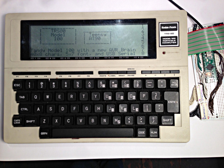
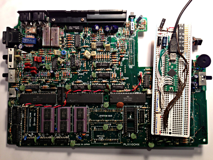
The TRS-80 Model 100 was introduced in 1983 and was one of the first notebook-style computers. It features an 8-bit processor and 32k of RAM. Trammel Hudson came across one of these and while it’s motherboard had failed, the LCD and keyboard were still working. He decided to take this non-working model and give a new brain. The original, bulky motherboard (check out all those through hole parts) was replaced with a Teensy ++ 2.0
There was a bit of a challenge with making the original LCD and keyboard work with the Teensy. He first identified how the LCD drivers worked and wrote libraries to replace them. The LCD did not have a character generator, so a font set had to be created.
Check out this project page for details on how it came together.
Many years I built electronics for Lostmachine Andy‘s fire effects on his awesome pirate ship for Burning Man.
The electronics from this old project were reused in several other propane fire art projects.
To get a better idea of Andy’s amazing Pirate Ship project, check out the video on his kickstarter page. The info about the fire effects starts at 2:58 into the video.
Here is a video where 1 of the 8 fire nozzles was tested in Andy’s driveway!
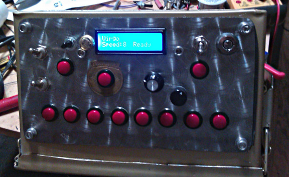
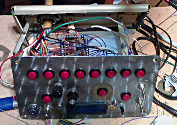
My little piece of this huge project is the circuit board, which you can see in the center of this nice metal box Andy machined.
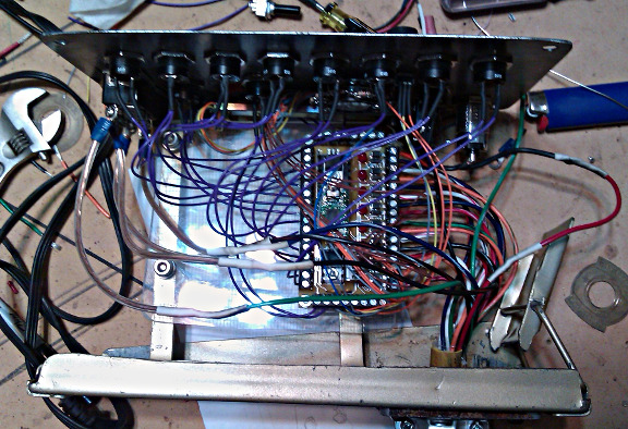
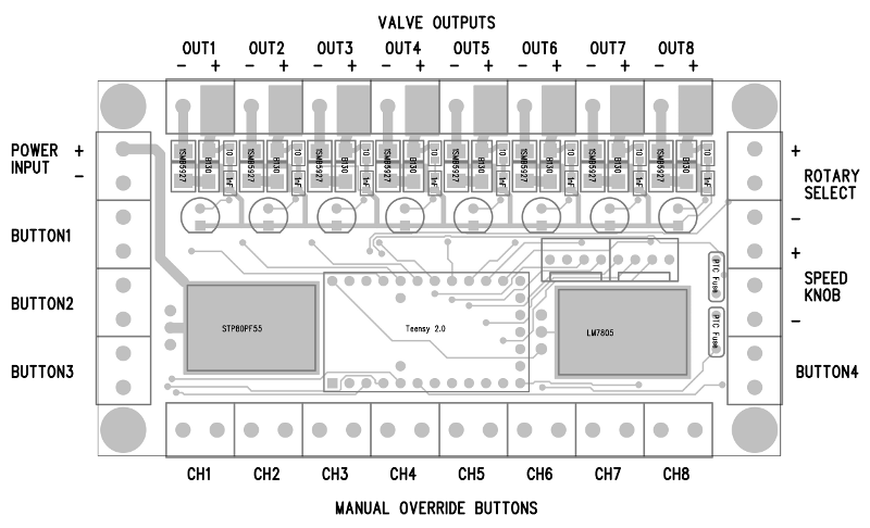
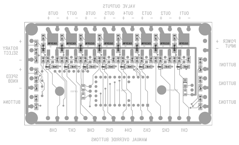
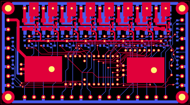
Here are images of the circuit board.
The 8 solenoid valves connect on the top edge. Eight manual fire pushbuttons connect on the bottom edge. Those pushbuttons directly turn on the transistor for each valve. Of course, the software running on a Teensy 2.0 can control the valves too. There’s inputs for 4 buttons and 2 knobs to the software. There’s a place to plug in a 16×2 LCD, which shows info about the sequence to be used.
Circuitry-wise, the board is pretty simple. There’s a big P-channel mosfet at the input, acting as a diode to protect against reverse polarity power. Each valve draws about 1.5 amps, so at 12 amps, a regular diode didn’t seem like a good idea. In the center is a Teensy 2.0 board in sockets, and to the right is a LM7805 regulator. The 5 volt power to the 2 knobs goes through little PTC fuses. The knobs and buttons just wire into analog and digital pins, through some little R-C filters, just in case there’s any radio frequency noise pickup. Since I’m not going to Burning Man this year and can’t be there to troubleshoot, I wanted to play it safe (and it only takes a few extra cheap parts).
On the top edge are the 8 transistor circuits. There too, I decided to play things safe, perhaps a bit overly cautious? The valves are switched with IRFR5305 P-channel mosfets. Rated at 31 amps, 55 volts, they’re a bit overkill. Then again, I wanted to make sure they wouldn’t get hot, so their on resistance of 0.065 ohms is nice. At 1.5 amps, that ought to be 0.15 watts, which isn’t much at all for a package with a metal tab. A lesser transistor would have worked, but might have needed a heatsink. This PCB was made at Sunstone and just barely fit into 9 square inches. Using heatsinks would have bumped the cost up to the next bracket, which is a lot more than the cost of these nicer transistors.
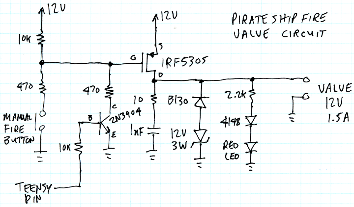
Andy was concerned about the valves switching quickly. So for the back-EMF catch diode, I used a B130 schottky in series with a 12 volt, 3 watt zener. That lets the valve create -12 volts while discharging, so it ought to switch from on-to-off about as far as off-to-on. We talked a bit about possibly using a very complex approach where the valves might be driven with about 50 volts until they get up to the correct current, and then sustain at the rated 12 volts. Yes, that’s risky, but I’m pretty sure I could do it safely. Maybe after the burn this year we’ll be able to play with the valves and experiment to see if forcing the valve to open and close faster than it can with only 12 volts actually allows any interesting fire effects?
A couple extra overly cautious things I did do were resistors to slow down the gate drive into the microseconds range (still far faster than any mechanical valve can move), and just to be extra cautious, I put a tiny R-C snubber on the output, just in case the transistor somehow switches faster that the reverse recovery time of those diodes. I guess over an amp of current flowing in an almost purely inductive load makes me a bit nervous. Those parts probably aren’t necessary and the 2 diodes are probably all the protection necessary from inductive spikes… but I wanted to play it extra safe since things are so hard to fix out on the playa at Burning Man (especially at night, when the fire will be in use).
So with all this circuitry hooked up, the good news is it’s all programmable with Arduino. Here’s the sketch I delivered to Andy. It reads a 12 position rotary knob and a speed pot, and plays 1 of the 12 sequences when a “Go” button is pressed. There’s a “stop” and “fire all” button, and the 4th button is unused.
While this code is fairly long, and a bit complex in the custom delay and other stuff near the end, I tried to keep the definition of the 12 sequences very simple. Just digitalWrite and the custom delay function.
#include <LiquidCrystal.h>
#include <Bounce.h>

// input pins
const int go_button_pin      = 4;
const int stop_button_pin    = 1;
const int all_button_pin     = 2;
const int speed_knob_pin     = 20;  // analog
const int rotary_select_pin  = 21; // analog

// output pins
const int valve1_pin         = 19;
const int valve2_pin         = 18;
const int valve3_pin         = 17;
const int valve4_pin         = 16;
const int valve5_pin         = 15;
const int valve6_pin         = 14;
const int valve7_pin         = 13;
const int valve8_pin         = 12;
const int lcd_rs_pin         = 5;
const int lcd_en_pin         = 6;
const int lcd_d4_pin         = 7;
const int lcd_d5_pin         = 8;
const int lcd_d6_pin         = 9;
const int lcd_d7_pin         = 10;
const int led_pin            = 11;

const byte valvelist[8] = {valve1_pin, valve2_pin, valve3_pin, valve4_pin,
                           valve5_pin, valve6_pin, valve7_pin, valve8_pin};

// unused pins
const int unused_button_pin  = 3;
const int unused1_pin        = 0;
const int unused2_pin        = 22;
const int unused3_pin        = 23;
const int unused4_pin        = 24;

// Objects for the buttons and display
Bounce go_button(go_button_pin, 10);
Bounce stop_button(stop_button_pin, 10);
Bounce all_button(all_button_pin, 10);
LiquidCrystal lcd(lcd_rs_pin, lcd_en_pin,
  lcd_d4_pin, lcd_d5_pin, lcd_d6_pin, lcd_d7_pin);


#define Pattern_Name_1 "Sweep Left+Right";
void play1()
{
  digitalWrite(valve1_pin, HIGH);
  if (delayCust(150, 100)) return;
  digitalWrite(valve1_pin, LOW);

  digitalWrite(valve2_pin, HIGH);
  if (delayCust(150, 100)) return;
  digitalWrite(valve2_pin, LOW);

  digitalWrite(valve3_pin, HIGH);
  if (delayCust(150, 100)) return;
  digitalWrite(valve3_pin, LOW);

  digitalWrite(valve4_pin, HIGH);
  if (delayCust(150, 100)) return;
  digitalWrite(valve4_pin, LOW);

  digitalWrite(valve5_pin, HIGH);
  if (delayCust(150, 100)) return;
  digitalWrite(valve5_pin, LOW);

  digitalWrite(valve6_pin, HIGH);
  if (delayCust(150, 100)) return;
  digitalWrite(valve6_pin, LOW);

  digitalWrite(valve7_pin, HIGH);
  if (delayCust(150, 100)) return;
  digitalWrite(valve7_pin, LOW);

  digitalWrite(valve8_pin, HIGH);
  if (delayCust(150, 100)) return;
  digitalWrite(valve8_pin, LOW);
}


#define Pattern_Name_2 "Sweep Right-Left"
void play2()
{
  digitalWrite(valve8_pin, HIGH);
  if (delayCust(150, 100)) return;
  digitalWrite(valve8_pin, LOW);

  digitalWrite(valve7_pin, HIGH);
  if (delayCust(150, 100)) return;
  digitalWrite(valve7_pin, LOW);

  digitalWrite(valve6_pin, HIGH);
  if (delayCust(150, 100)) return;
  digitalWrite(valve6_pin, LOW);

  digitalWrite(valve5_pin, HIGH);
  if (delayCust(150, 100)) return;
  digitalWrite(valve5_pin, LOW);

  digitalWrite(valve4_pin, HIGH);
  if (delayCust(150, 100)) return;
  digitalWrite(valve4_pin, LOW);

  digitalWrite(valve3_pin, HIGH);
  if (delayCust(150, 100)) return;
  digitalWrite(valve3_pin, LOW);

  digitalWrite(valve2_pin, HIGH);
  if (delayCust(150, 100)) return;
  digitalWrite(valve2_pin, LOW);

  digitalWrite(valve1_pin, HIGH);
  if (delayCust(150, 100)) return;
  digitalWrite(valve1_pin, LOW);
}

#define Pattern_Name_3 "Alt Side-Side"
void play3()
{
  for (int count=0; count < 6; count++) {
    digitalWrite(valve1_pin, HIGH);
    digitalWrite(valve2_pin, HIGH);
    digitalWrite(valve3_pin, HIGH);
    digitalWrite(valve4_pin, HIGH);
    if (delayCust(90, 75)) return;
    digitalWrite(valve1_pin, LOW);
    digitalWrite(valve2_pin, LOW);
    digitalWrite(valve3_pin, LOW);
    digitalWrite(valve4_pin, LOW);

    digitalWrite(valve5_pin, HIGH);
    digitalWrite(valve6_pin, HIGH);
    digitalWrite(valve7_pin, HIGH);
    digitalWrite(valve8_pin, HIGH);
    if (delayCust(90, 75)) return;
    digitalWrite(valve5_pin, LOW);
    digitalWrite(valve6_pin, LOW);
    digitalWrite(valve7_pin, LOW);
    digitalWrite(valve8_pin, LOW);
  }
}

#define Pattern_Name_4 "Alt Odd-Even"
void play4()
{
  for (int count=0; count < 6; count++) {
    digitalWrite(valve1_pin, HIGH);
    digitalWrite(valve3_pin, HIGH);
    digitalWrite(valve5_pin, HIGH);
    digitalWrite(valve7_pin, HIGH);
    if (delayCust(90, 75)) return;
    digitalWrite(valve1_pin, LOW);
    digitalWrite(valve3_pin, LOW);
    digitalWrite(valve5_pin, LOW);
    digitalWrite(valve7_pin, LOW);

    digitalWrite(valve2_pin, HIGH);
    digitalWrite(valve4_pin, HIGH);
    digitalWrite(valve6_pin, HIGH);
    digitalWrite(valve8_pin, HIGH);
    if (delayCust(90, 75)) return;
    digitalWrite(valve2_pin, LOW);
    digitalWrite(valve4_pin, LOW);
    digitalWrite(valve6_pin, LOW);
    digitalWrite(valve8_pin, LOW);
  }
}

#define Pattern_Name_5 "Mid to Outside";
void play5()
{
  digitalWrite(valve4_pin, HIGH);
  digitalWrite(valve5_pin, HIGH);
  if (delayCust(80, 25)) return;

  digitalWrite(valve3_pin, HIGH);
  digitalWrite(valve6_pin, HIGH);
  if (delayCust(80, 25)) return;

  digitalWrite(valve2_pin, HIGH);
  digitalWrite(valve7_pin, HIGH);
  if (delayCust(80, 25)) return;

  digitalWrite(valve1_pin, HIGH);
  digitalWrite(valve8_pin, HIGH);
  if (delayCust(80, 25)) return;

  digitalWrite(valve4_pin, LOW);
  digitalWrite(valve5_pin, LOW);
  if (delayCust(80, 25)) return;

  digitalWrite(valve3_pin, LOW);
  digitalWrite(valve6_pin, LOW);
  if (delayCust(80, 25)) return;

  digitalWrite(valve2_pin, LOW);
  digitalWrite(valve7_pin, LOW);
  if (delayCust(80, 25)) return;

  digitalWrite(valve1_pin, LOW);
  digitalWrite(valve8_pin, LOW);
}

#define Pattern_Name_6 "(unused) Six"
void play6()
{
  digitalWrite(valve1_pin, HIGH);
  if (delayCust(25, 50)) return;
  digitalWrite(valve1_pin, LOW);

}

#define Pattern_Name_7 "Random, 1 valve"
void play7()
{
  for (byte i=0; i<20; i++) {
    byte myValve = valvelist[random(0, 8)];
    digitalWrite(myValve, HIGH);
    if (delayCust(50, 75)) return;
    digitalWrite(myValve, LOW);
  }
}

// this is a comment
// You can type a description
// Or deep thoughts
#define Pattern_Name_8 "Random, 2 valves"
void play8()
{
   for (byte i=0; i<20; i++) {
    byte myValve1 = valvelist[random(0, 8)];
    byte myValve2 = myValve1;
    while (myValve2 == myValve1) {
      myValve2 = valvelist[random(0, 8)];
    }
    digitalWrite(myValve1, HIGH);
    digitalWrite(myValve2, HIGH);
    if (delayCust(50, 75)) return;
    digitalWrite(myValve1, LOW);
    digitalWrite(myValve2, LOW);
  }
}

#define Pattern_Name_9 "Random, 2 Valves";
void play9()
{
  byte prev1 = 100;
  byte prev2 = 101;
  byte myValve1 = 102;
  byte myValve2 = 103;
  for (byte i=0; i<20; i++) {
    while (myValve1 == prev1 || myValve1 == prev2 || myValve2 == prev1 || myValve2 == prev2) {
      myValve1 = valvelist[random(0, 8)];
      myValve2 = myValve1;
      while (myValve2 == myValve1) {
        myValve2 = valvelist[random(0, 8)];
      }
    }
    digitalWrite(myValve1, HIGH);
    digitalWrite(myValve2, HIGH);
    if (delayCust(50, 75)) return;
    digitalWrite(myValve1, LOW);
    digitalWrite(myValve2, LOW);
    prev1 = myValve1;
    prev2 = myValve2;
  }
}

#define Pattern_Name_10 "Pi Pattern"
void play10()
{
  digitalWrite(valve3_pin, HIGH);
  if (delayCust(50, 75)) return;
  digitalWrite(valve3_pin, LOW);
  if (delayCust(50, 75)) return;

  digitalWrite(valve1_pin, HIGH);
  if (delayCust(50, 75)) return;
  digitalWrite(valve1_pin, LOW);
  if (delayCust(50, 75)) return;

  digitalWrite(valve4_pin, HIGH);
  if (delayCust(50, 75)) return;
  digitalWrite(valve4_pin, LOW);
  if (delayCust(50, 75)) return;

  digitalWrite(valve1_pin, HIGH);
  if (delayCust(50, 75)) return;
  digitalWrite(valve1_pin, LOW);
  if (delayCust(50, 75)) return;

  digitalWrite(valve5_pin, HIGH);
  if (delayCust(50, 75)) return;
  digitalWrite(valve5_pin, LOW);
  if (delayCust(50, 75)) return;

  digitalWrite(valve8_pin, HIGH);
  if (delayCust(50, 75)) return;
  digitalWrite(valve8_pin, LOW);

}

#define Pattern_Name_11 "(unused) Eleven"
void play11()
{

}

#define Pattern_Name_12 "(unused) Twelve"
void play12()
{

}


// initialize hardware - only done once at bootup
void setup() {
  pinMode(go_button_pin, INPUT_PULLUP);
  pinMode(stop_button_pin, INPUT_PULLUP);
  pinMode(all_button_pin, INPUT_PULLUP);
  pinMode(unused_button_pin, INPUT_PULLUP);
  pinMode(unused1_pin, INPUT_PULLUP);
  pinMode(unused2_pin, INPUT_PULLUP);
  pinMode(unused3_pin, INPUT_PULLUP);
  pinMode(unused4_pin, INPUT_PULLUP);
  pinMode(valve1_pin, OUTPUT);
  pinMode(valve2_pin, OUTPUT);
  pinMode(valve3_pin, OUTPUT);
  pinMode(valve4_pin, OUTPUT);
  pinMode(valve5_pin, OUTPUT);
  pinMode(valve6_pin, OUTPUT);
  pinMode(valve7_pin, OUTPUT);
  pinMode(valve8_pin, OUTPUT);
  lcd.begin(16, 2);
}

int prev_num = -100;
int prev_knob_reading = -100;


void loop() {
  // first, update the status of the buttons
  go_button.update();
  stop_button.update();
  all_button.update();

  // the "ALL" button is highest priority
  if (all_button.read() == LOW) {
    lcd.clear();
    lcd.print(" All Valves ON");
    digitalWrite(valve1_pin, HIGH);
    digitalWrite(valve2_pin, HIGH);
    digitalWrite(valve3_pin, HIGH);
    digitalWrite(valve4_pin, HIGH);
    digitalWrite(valve5_pin, HIGH);
    digitalWrite(valve6_pin, HIGH);
    digitalWrite(valve7_pin, HIGH);
    digitalWrite(valve8_pin, HIGH);
    while (all_button.read() == LOW) {
      all_button.update();
      // do nothing, just wait for button release
    }
    digitalWrite(valve1_pin, LOW);
    digitalWrite(valve2_pin, LOW);
    digitalWrite(valve3_pin, LOW);
    digitalWrite(valve4_pin, LOW);
    digitalWrite(valve5_pin, LOW);
    digitalWrite(valve6_pin, LOW);
    digitalWrite(valve7_pin, LOW);
    digitalWrite(valve8_pin, LOW);
    lcd.clear();
    prev_num = -100;
    prev_knob_reading = -100;
  }

  // when not doing anything, read the knobs
  // and show status info on the LCD
  int rotary_reading = analogRead(rotary_select_pin);

  int num;
  const char *name;
  if (rotary_reading < 47) {
    num = 1;
    name = Pattern_Name_1;
  } else if (rotary_reading < 140) {
    num = 2;
    name = Pattern_Name_2;
  } else if (rotary_reading < 233) {
    num = 3;
    name = Pattern_Name_3;
  } else if (rotary_reading < 326) {
    num = 4;
    name = Pattern_Name_4;
  } else if (rotary_reading < 419) {
    num = 5;
    name = Pattern_Name_5;
  } else if (rotary_reading < 512) {
    num = 6;
    name = Pattern_Name_6;
  } else if (rotary_reading < 605) {
    num = 7;
    name = Pattern_Name_7;
  } else if (rotary_reading < 698) {
    num = 8;
    name = Pattern_Name_8;
  } else if (rotary_reading < 791) {
    num = 9;
    name = Pattern_Name_9;
  } else if (rotary_reading < 884) {
    num = 10;
    name = Pattern_Name_10;
  } else if (rotary_reading < 977) {
    num = 11;
    name = Pattern_Name_11;
  } else {
    num = 12;
    name = Pattern_Name_12;
  }
  if (num != prev_num) {
    lcd.setCursor(0, 0);
    lcd.print(name);
    for (int i=strlen(name); i < 16; i++) {
      lcd.print(' ');
    }
    prev_num = num;
  }

  get_speed();
  lcd.setCursor(9, 1);
  lcd.print("Ready");

  if (go_button.fallingEdge()) {
    lcd.setCursor(9, 1);
    lcd.print("Running");
    switch (num) {
      case 1: play1(); break;
      case 2: play2(); break;
      case 3: play3(); break;
      case 4: play4(); break;
      case 5: play5(); break;
      case 6: play6(); break;
      case 7: play7(); break;
      case 8: play8(); break;
      case 9: play9(); break;
      case 10: play10(); break;
      case 11: play11(); break;
      case 12: play12(); break;
      default: play1();
    }
    // after playing, always make sure all valves are off
    digitalWrite(valve1_pin, LOW);
    digitalWrite(valve2_pin, LOW);
    digitalWrite(valve3_pin, LOW);
    digitalWrite(valve4_pin, LOW);
    digitalWrite(valve5_pin, LOW);
    digitalWrite(valve6_pin, LOW);
    digitalWrite(valve7_pin, LOW);
    digitalWrite(valve8_pin, LOW);
    // and reset the state, so the screen fully redraws
    lcd.clear();
    prev_num = -100;
    prev_knob_reading = -100;
  }

  delay(10);
}


// Read the speed knob.  This is a bit tricky, because we don't want to
// rapidly alternate between two speed settings if the knob is exactly at
// the mid-point and a tiny bit of noise changes the reading slightly.
// So instead, this code remember the previous setting and implements a
// tiny dead band (hysteresis) to so the user always sees a smooth
// appearance on the LCD.
//
byte get_speed(void)
{
  static byte knob_speed = 1;
  int knob_reading = analogRead(speed_knob_pin);
  if (knob_reading < prev_knob_reading - 2 || knob_reading > prev_knob_reading + 2) {
     lcd.setCursor(0, 1);
     lcd.print("Speed:");
     knob_speed = (knob_reading / 94) + 1;  // range is 1 to 11
     lcd.print((int)knob_speed);
     if (knob_speed < 10) lcd.print(" ");
     prev_knob_reading = knob_reading;
  }
  return knob_speed;
}


// Delay based on speed setting.  "mult" is a multiplier for
// the speed, and "fixed" is a fixed delay that is always
// added regardless of the speed setting.  This fancy code
// allows the delay setting to change, and also aborts if the
// STOP or ALL buttons are pressed.
//
boolean delayCust(int mult, int fixed)
{
  unsigned long us = micros();
  unsigned long elapsed_ms = 0;
  unsigned long target_ms;

  while (1) {
    target_ms = (11 - get_speed()) * mult + fixed; // moving target
    if (elapsed_ms >= target_ms) return false;  // delay completed
    if (micros() - us >= 1000) {
      elapsed_ms = elapsed_ms + 1;
      us = us + 1000;
    }
    if (stop_button.update()) return true; // delay interrupted
    if (all_button.update()) return true;
  }
}
The last bit of technical info to share is the PCB gerber files, which were sent to Sunstone. Here are the PCB gerber files.
If you use these files, please be aware 1 small error was discovered. The power for the LCD was mistakenly connected to +12 volts. If you use a LCD, you must cut that trace and solder a wire to the +5 volt output of the LM7805. Other that that 1 error, the board works great.
This article was originally published on the DorkbotPDX website, on August 23, 2011. In late 2018, DorkbotPDX removed its blog section. An archive of the original article is still available on the Internet Archive. I am republishing this article here, so the info and files for this project can be found and used by anyone wanting to build it.
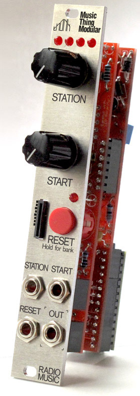
Tom Whitwell of Music Thing Modular created Radio Music, a DIY virtual radio module.
Radio Music is not a radio. It is a eurorack module sample player that behaves like a radio and is designed to be a source of unexpected audio.
This module works on a series of banks and stations, just like a radio. It uses a Teensy 3.2 to play files from an SD card to simulate a voltage controlled AM/FM/Shortwave/Time Travel radio.
This module is extremely versatile and can be turned into a different module simply by changing the firmware. The Chord Organ firmware that synthesizes chords.
Radio Music is open hardware with extensive documentation available on GitHub.
To learn more about Radio Music, check out this great 5-part series from Voltage Control Lab that covers topics such as preparing samples and alternative firmware.
You can purchase a Radio Music DIY kit from Thonk. It includes all the parts needed to build your own. The kit features maker-friendly though hole parts. Here’s a time lapse video of the assembly
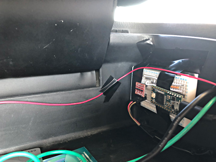
The ’97 Impreza uses an engine control unit (ECU) and provides a diagnostic connector for external communication. P1ckachu built a diagnostic interface device, got a dump of the ECU’s firmware, and reverse engineered the binary to figure out how to disable the speed limiter. The custom interface uses a Teensy 3.2 and logic level converter to convert the Teensy’s 3.3v to the car’s 5v.
P1kachu has a great write up the project on this page.
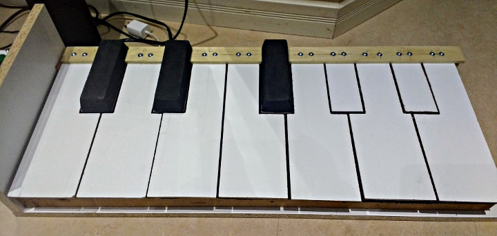
alpage built a large keyboard to be played while doing a handstand.
When his handstand coach asked if anyone could build a piano that could be played with his feet while upside down, alpage stepped up to the task. Using a Teensy 3.5 and wave table synthesis in the Audio Library, the piano came together. The piano plays chords and has 4 different voices.
You can watch the keyboard being played with feet while in a handstand in this Facebook video.
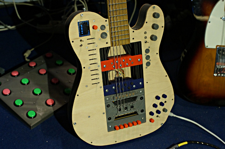
Frank Piesik built the ElektroCaster, an awesome open, modular guitar-synth.
The incredibly versatile ElektroSynth is playable as both an electric guitar and and synth, and also has a pretty impressive list of features such as:
Parametric OpenScad modelling (changable string count, scale, space between strings,…)
Fully controllable RGB-Led-iluminated Fretboard (Only the first 17 frets for now, but easily exendable)
Touch-sensing-frets
Long scale (700mm) for low tunings
Two micros, one for audio an one for everything else.
Per string signal path
hexaphonic pickup
hex-preamp
This project came about because Frank had always wanted an illuminated fret-board to display information such as scales and sequences. Armed with a 3D printer, CNC router and other maker tools, he set out to build a guitar from scratch.
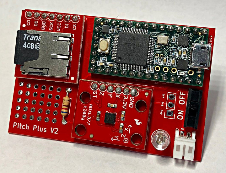
Brett Garberman is part of a team that developed Pitch Plus, a wearable device for Little League baseball pitchers
Repetitive pitching is a leading cause of non-contact injuries in Little League. Monitoring the number of pitches per player for a game, season, or month can be a challenging task. The Medical Device club at the University of Pennsylvania’s Penn Health-Tech initiative developed Pitch Plus to help with monitor the pitching activity of Little League players.
The PitchPlus uses a Teensy 3.2 as its processor and also has an ADXL377 accelerometer. The device collects data on the pitching activity of the player and stores it on an SD card. Not only does it record pitch count, but the level of force in the pitch as well. The data can then be imported into MATLAB for analysis. It also includes a Bluetooth module that allows the data to be live-streamed for live visualization. This allows for coaches to better monitor players and limit play time when needed to prevent injury.
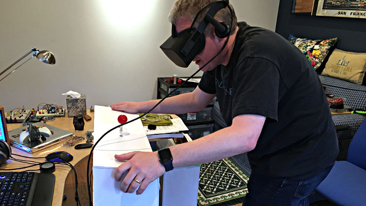
Jeremy Williams built PinSim, a cabinet controller for virtual reality pinball to get much more realistic game playing experience.
Jeremy, a huge pinball enthusiast, knew he had to build a cabinet when he saw Pinball FX 2 VR at Oculus Days. Digital pinball games have been around for quite a while, but as Jeremy noted, one of the problems with them is that your perspective is static. Virtual reality (VR) pinball games allows users to change their perspective while playing, allowing for more finesse.
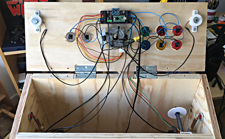
The PinSim cabinet improves the game play experience by adding a few elements that are crucial for realistic pinball play such as tactile controls, “non-clicky” buttons for the flippers, and an accelerometer-based nudge system. Not only can you nudge the cabinet to move the ball, but if you nudge too much, you’ll tilt.
For the electronics a Teensy-LC using the MSF-XINPUT library by Zack Littell is used to emulate an Xbox 360 gamepad.
Build instructions for the cabinet can be found over on Tested. Code for the project can be found on GitHub. Over on the forum there’s a thread helping a user get all the libraries need to compile the PinSim code.
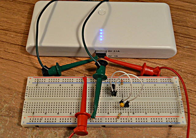
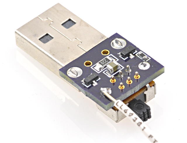
I purchased a cheap USB power pack, thinking it would be ideal for powering small projects. But it automatically shuts off if the device isn’t drawing a lot of power, since it’s meant for charging cell phones.
Here’s a 2 transistor circuit that keeps it on with very little battery drain by using brief pulses.
I wish I would have thought of this idea, but it came from this forum post by “Jp3141”. The battery pack automatically turns off if it doesn’t see a high current draw. But drawing a high current for only a brief time is enough to keep its internal timer going.
First, I did some experimenting and found a 22 ohm resistor keeps the power on indefinitely. A 27 ohm resistor kept it on for 19 seconds. With no load, it stays on for only 13 seconds. So a 22 ohm load it is!
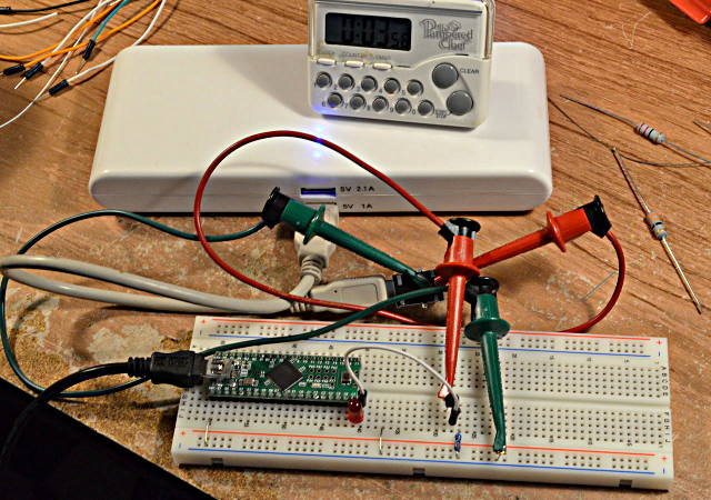
Just connecting a 22 ohm resistor to the 5 volt power is a pretty heavy load that would drain the battery. A 22 ohm resistor also burns about 1.1 watts, so it gets HOT. But the load doesn’t need to be on most of the time. The next step was connecting a Teensy and transistor circuit to turn on the load under software control.
Here the 5V pin drives a LED in series with a NPN base-emitter junction, to apply about 2.3 volts to a 10 ohm resistor. Of course, the NPN transistor has high current gain, so most of the 230 mA that flows through the 10 ohm resistor comes from the battery through the collector.
A little experimenting determined pretty quickly that pulses in the 8 to 10 ms range usually keep the battery pack on, but it sometimes turns off after a couple minutes. 20 ms seems very stable.
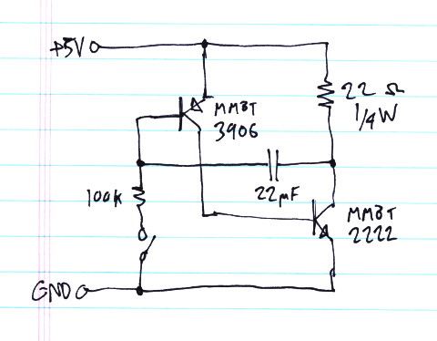
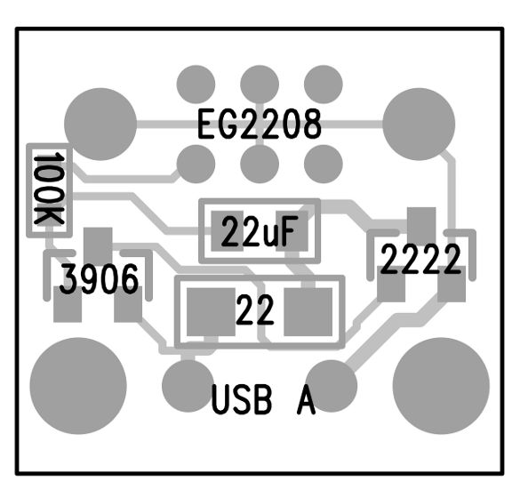
Knowing 20 ms is needed, I switched from using the Teensy++ to this simple 2 transistor oscillator:
A quick napkin calculation seemed to suggest this would need a really large capacitor. But with a little fiddling, it turned out 22 uF was enough. This circuit creates a pulse slight over 20 ms approximately every 1.4 seconds.
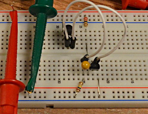
Here’s another close-up of the circuit on the breadboard. Just 2 transistors, 1 capacitor, and 2 resistors.
I let this run for about half an hour, with the battery pack happily remaining on the whole time.
The average battery current is ~3.5 mA.
While the transistors are on, the current is approx 222 mA (4.9V on 22 ohms). But the duty cycle is about 1.6%.
Inside the pack, a switching power supply is running to step up the batteries from 3.7 to 5 volts, and it’s powering those 4 blue LEDs. The internal stuff inside the pack probably wastes a lot more than only 3.5 mA.
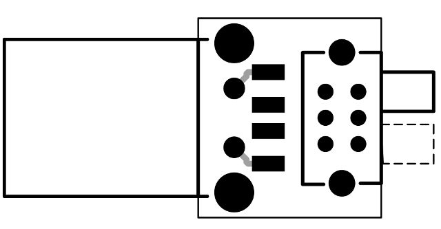
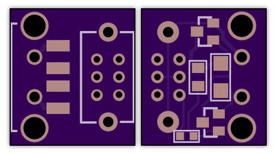
Of course, then I did a quick PCB layout. I added a switch in series with the 100K resistor, so it can be left plugged in and turned off to allow the battery pack to shut itself off. It’s a tiny board, only about the size of the USB connector itself.
I sent the files in to OSH Park. Here’s their preview.
Here’s the board on their site, if anyone else wants to build this:
If you need to tune the timing for a different battery pack, increasing the capacitor makes the pulse wider and lengthens the time between pulses. Decreasing the 100K resistor makes the pulse occur more frequently, without changing the width of the pulse.
EDIT: My battery pack turned off a couple times times after many minutes. I increased the capacitor to 47 uF and it ran for an hour. 22 uF might be a little on the low side? If you build this circuit, a little tweaking on the capacitor or resistor values might be needed if your battery pack is different.
EDIT AGAIN: Later I purchased an identical-looking battery pack, except it had black plastic instead of white. It turned out to have a completely different power detecting scheme. The pulses wouldn’t work. This little circuit clearly doesn’t apply to every battery pack, but it worked very well on the earlier white one.
This article was originally published on the DorkbotPDX website, on November 5, 2013. In late 2018, DorkbotPDX removed its blog section. An archive of the original article is still available on the Internet Archive. I am republishing this article here, so anyone still using these battery packs can try this circuit.
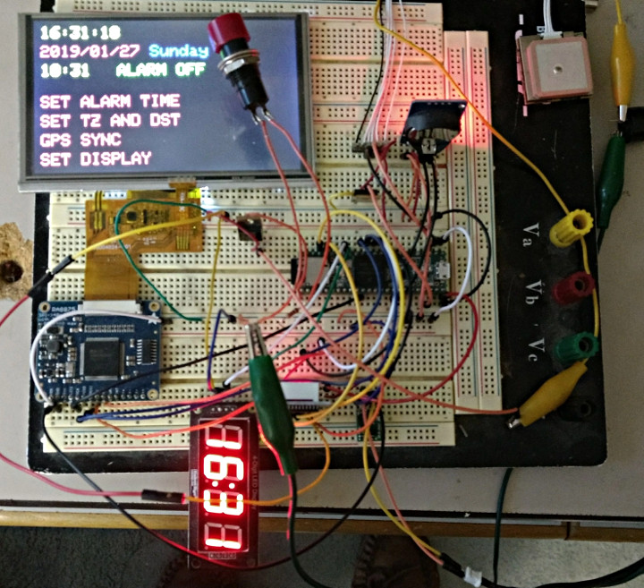
An alarm clock with everything! Has a high accuracy temperature compensated clock (DS3231), automatic sync to GPS time, large touchscreen user interface, handling of time zones and daylight savings time.
Code and schematics for the project are available on the ElektorLabs project page, but it looks like you will have to create an Elektor account to access them.