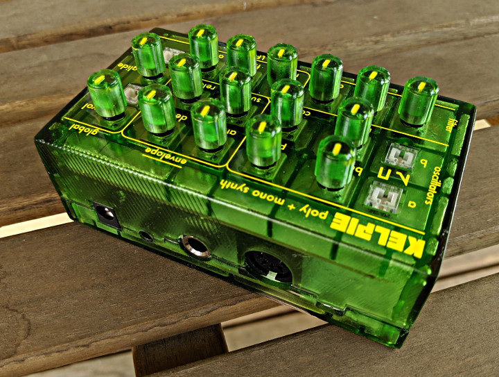
Kenneth Marut designed and developed the KELPIE, a portable monphonic and polyphonic digital synthesizer.
This incredible little synth is a great way for beginners to get started in the world of synthesizers. It only requires a power supply and a MIDI connection that can plug right into MIDI device such as a keyboard. It also include a 1/4″ mono output and 1/8″ stereo output. The workmanship and attention to detail on this project is impressive.
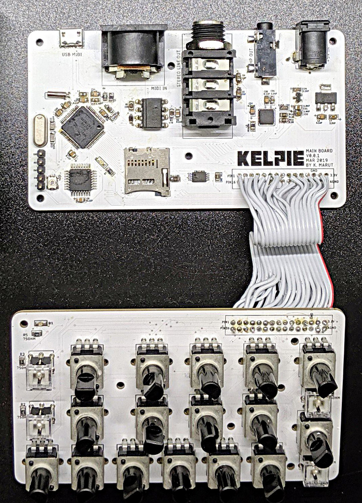
Kenneth rolled his own Teensy 3.2 and Audio Shield to create the KELPIE and used Teensy Audio Library. It includes USB input so that you can update the code.
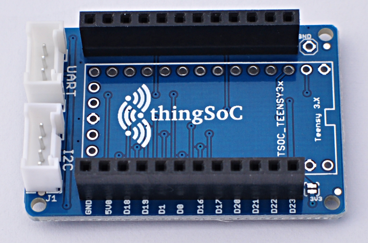
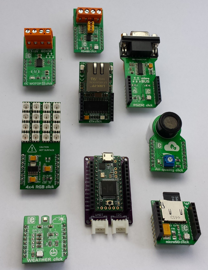
Pattern Agents have developed TSOC_Teensy3x, a thingSoC adapter that allows you to connect thingSoC, Mikrobus, and Grove System modules using a Teensy 3.2
This clever adapter can be used with any thingSoC, Mikrobus, or Grove System modules. It also works with a number of different IoT comptaible wireless radio modules as well as many different input and output sensors and modules giving you a lot of flexibility with a variety of sensors and actuators.
Additional details on the project are available on GitHub.
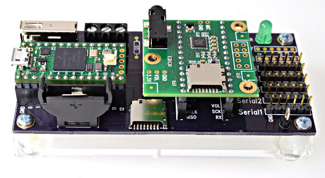
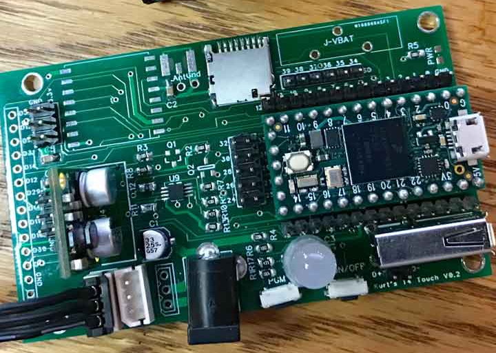
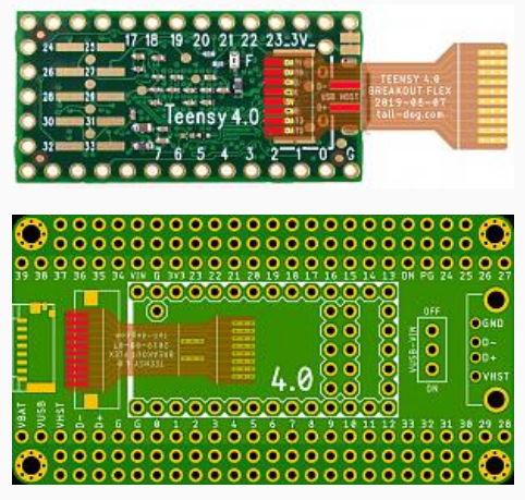
During the Teensy 4.0 beta test we made these breakout boards, to easily test hardware features. They were also sent to Hackaday, Hackster, and Hackspace Magazine for reviews.
Now we’re sharing all the info, so you can make your own copy of this breakout board!
Breakout Board Features
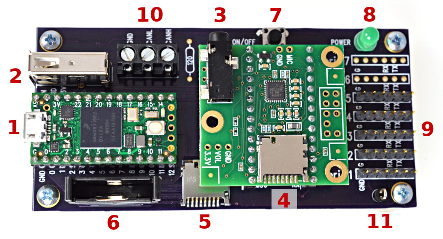
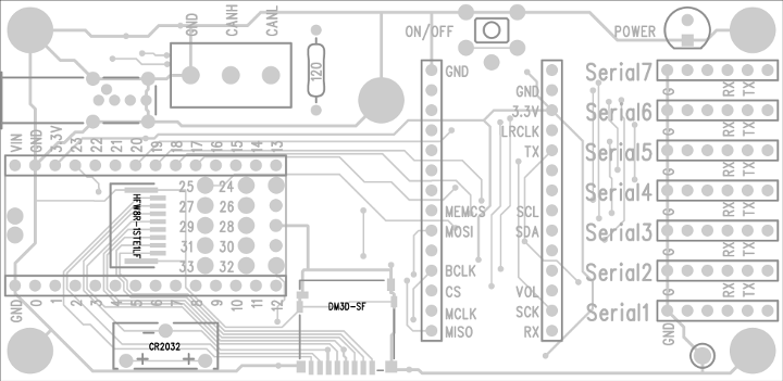
First, let’s look at the main features.
Main USB for Teensy 4.0. The entire board gets power from this USB connector, so it must be plugged in for the eval board to work.
Second USB host port. To test this, plug in a USB keyboard or MIDI keyboard or drum pad. In Arduino, click File > Examples > USBHost_t36 > Test for a simple program which responds to events from those types of USB devices. The eval board has a TPS2055A current limit chip, which allows most USB devices to be hot plugged while running from USB power provided over the main USB port.
Audio shield output. Plug in headphones or computer speakers. Recommend running File > Examples > Audio > Synthesis > Guitar to test the audio output.
SD card accessed by SPI with pin 10 for CS. The eval kit comes with a 32 GB card pre-loaded with 4 public domain music files. Recommend running File > Examples > Audio > WavFilePlayer for a first test.
SD card accessed by SDIO (4 bit). To test this, run any of the SD library examples. Edit the chip select pin to BUILTIN_SDCARD. An 8 pin flat flex cable connects between the Teensy 4.0 and peripheral board to provide access to the SDIO pins.
Coin cell holder (CR2032 type battery), for RTC backup. Run File > Examples > Time > TimeTeensy3 to access the RTC date/time.
Power On/Off button. Hold for 5 seconds to completely shut off 3.3V power. Press for 1/2 second to turn back on. If a coin cell is installed, the power on/off state will be retained when you disconnect the USB cable. Without the coin cell to maintain power management state, the 3.3V power will default to “on” when power is applied.
Power LED, to visually confirm if the 3.3V power is turned on.
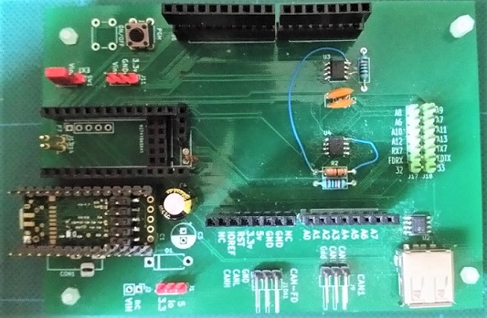
Serial1 to Serial7. These 6 pin headers mate with the commonly available FTDI TTL-level cables, and numerous boards following that 6 pin format. For a quick test program, click File > Examples > Teensy > Serial > EchoBoth. If using Serial2 or higher, edit the define in that program.
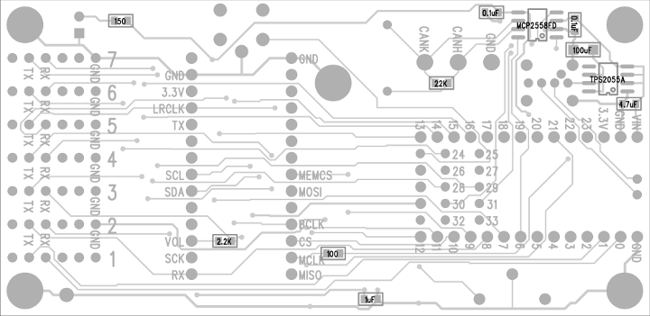
CAN FD port. Use the FlexCAN_t4 library to access this port. Unfortunately, the labels printed on the eval board are backwards. On the original boards (shown in these photos), the center pin labeled “CANL” is actually “CANH”, and the right hand pin labeled “CANH” is actually “CANL”. The shared PCB files have this error corrected. If your CAN bus requires a termination, a 120 ohm resistor can be soldered to the eval board.
Ground test point. Handy if you wish to make measurements with a voltmeter or oscilloscope. 🙂
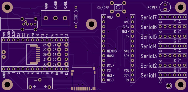
Circuit Board
The PCB is available as an OSH Park shared board. You can buy it from OSH Park, or use the Download button on that page to get the PCB gerber files.
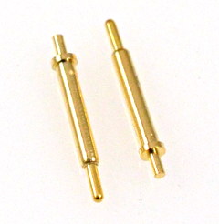
Connections to Teensy 4.0 Bottom Side
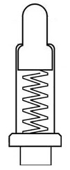
To connect to the bottom side of Teensy 4.0, the breakout board uses these spring-loaded pogo pins. Either 12 to 12.5 mm height can be used for the pins which touch the flat surface mount pads. 12.5 works best to contact to the On/Off and VBAT pins.
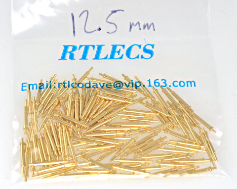
These pogo pins were purchased from RTLECS. (new RTLECS link) RTLECS sells on Aliexpress, Ebay and maybe other sites. If you have trouble finding them, the ones we used for the beta test came in this bag with contact info.
While there are 14 locations to solder these these pogo pins, Teensy pins 26, 27, 32, 33 are not routed on the breakout board. You only need 10 pogo pins to fully utilize all the breakout board features. Many of the ones built for the beta test had only 6 pogo pins, leaving off the 4 pins to for Serial6 & Serial7.
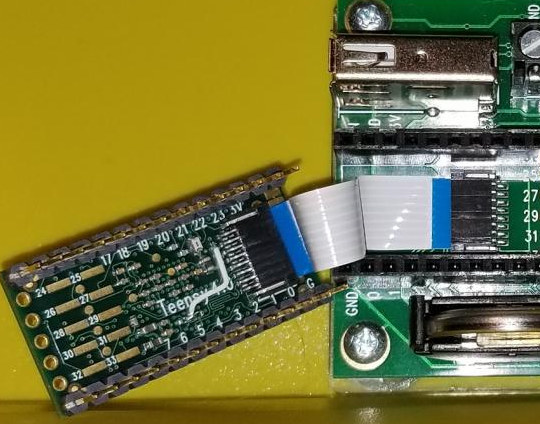
The 8 pins for native SD card support are connected by a FFC (flat flex cable) between Teensy 4.0 and the breakout board.
Credit to Defragster for sharing this photo on the forum. Also in this photo you can see one of the earlier beta test boards, which had a white wire soldered to the bottom to correct a brown-out restart problem discovered during beta testing. The final Teensy 4.0 boards have this wire routed on layer 3 (of 6) inside the PCB.
Parts List
Here is a complete list of parts needed to fully build the breakout board. Some of these parts may be left off if you do not need all the breakout board features.
To build the breakout board, first solder the bottom side parts.
When building the top side, first solder the FFC connector and SD socket, if you wish the use the native SD card.
Before soldering any other through-hole parts, solder the pogo pins. Getting these 12.5 mm tall pins aligned at a right angle to the PCB is tricky. The beta boards were held in a Stick Vise to keep the board flat with the table facing top side up and the surface covered with extra liquid flux, then the pins inserted and heated from their side while a small amount of solder was applied. They take quite some time to cool down. Use caution to avoid burned fingers!
After soldering the pogo pins, the rest of the through-hole parts can be soldered in any order. The 14 pins sockets make a nice a temporary alignment tool to hold the 6 pin headers straight. Placing your Teensy into the 14 pin sockets during soldering guarantees they are aligned so it will later fit properly.
Acrylic Base
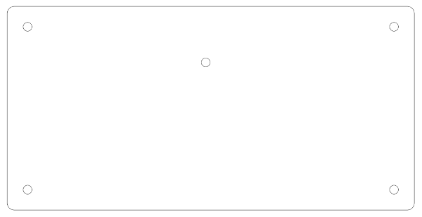
The final (optional) piece is this laser cut acrylic base.
The file used for these as SVG (zip download) can be used to get a proper fit. After laser cutting, the 5 holes were threaded with a #4-40 tap.
Tall Dog is working on a breakout board for Teensy 4.0, which you will be able to buy as a kit. They shared this preliminary image on the forum. This is still in the planning stage, so the final product may look different.
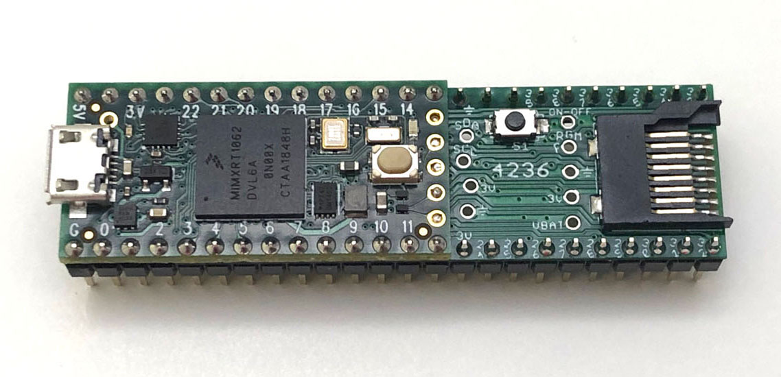
FRDM4236 Board
Felix (aka Trainer2Edu) created this add-on board which solders to the bottom side of Teensy 4.0
Their prior float was controlled by the Vixen X-mas lighting software. For 2012, Laurence wanted to make the float interactively respond to sounds. Tobias investigated different software and found excellent sound processing software, but no way to interface it to Vixen or last year’s firmware using Renard protocol. All sound processing software works with MIDI, so I decided to reprogram the controllers.
I wrote the MIDI firmware, just in time for their float kick-off party where the announce the winners of a contest for who will ride on the float. Lots of pictures and info on that Core77 page. This blog is about the technical details, making the el wires respond to MIDI control this year.
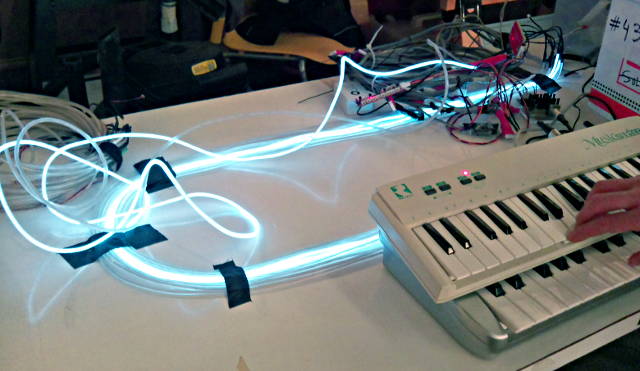
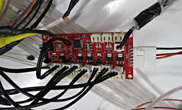
The el wires are controlled by this modified Sparkfun el wire sequencer.
This is the same board that had many problems last year. You can see in the photo 3 of the triacs blew on this board and were replaced with TO-92 through hole versions.
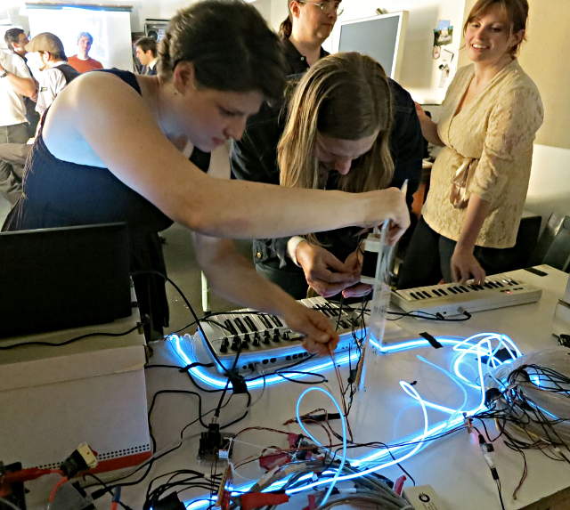
Here are Laurence Sarrazin and Tobias Berblinger reprogramming the sequencers, while Kathryn tries “playing” the lights.
The float runs on 15 sequencers, with 5 plexiglass panels having 3 sequencers and 3 cool neon “big boy” inverters per panel.
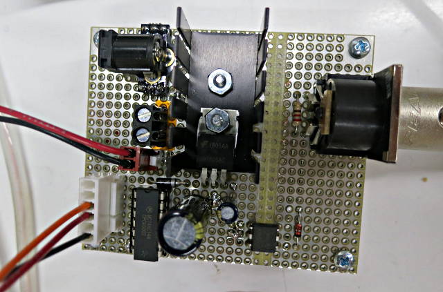
Here is the actual hardware I built for this year.
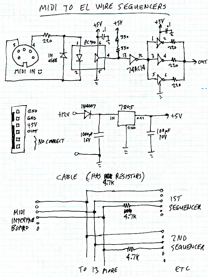
There’s no microcontroller. It just takes MIDI IN, goes through an opto-coupler, and then buffers the signal. Most of the space is a simple linear regulator to make 5 volts to send to the sequencers. Here’s a schematic:
An important point is the 4.7K resistors in the cable. The sequencers have AVR chips running at 3.3 volts, so these resistors prevent the 5 volt signal from damaging them.
The same signal goes to all 15 boards. Jumpers on the edge of the board configure which 8 notes each board will “play”.
The firmware only listens for MIDI channel #1. It is “velocity sensitive”, with the following code:
uint8_t midi2intensity(uint8_t velocity)
{
        if (velocity < 6) return 0;
        if (velocity < 12) return 1;
        if (velocity < 18) return 2;
        if (velocity < 24) return 3;
        if (velocity < 30) return 4;
        if (velocity < 36) return 5;
        if (velocity < 42) return 6;
        if (velocity < 48) return 7;
        return 8;
}
Intensity 8 corresponds to fully on. Lower numbers, from 1 to 7, output PWM-like drive to the triacs for dimming.
The idea behind these scalings is most of the MIDI velocity range will make the el wires fully illuminate. El wire isn’t terribly bright anyway. But if someday dimming effects are desired, that low section of the range can be used (without having to reprogram all 15 boards again).
Unfortunately, the Sparkfun sequencer lacks any information about the phase of the AC waveform to the el wire, so the pulses must be many cycles instead of switching individual cycles (you don’t want to do fractional-cycle dimming, as would be done on resistive or inductive loads). The lowest couple intensities sometimes flicker as a result.
Here is the source code which runs on those sequencer boards.
This article was originally published in May 2012 (archive.org link) on the DorkbotPDX site. Since then, the DorkbotPDX blog section has vanished. I’m reposting it here with slight edits, to preserve the info. Today Teensy 3.6 supports USB host MIDI (and many keyboards no longer have 5 pin DIN MIDI connectors, only USB), and LED strips are now far more popular than el wire, but perhaps this old info and code may still be helpful for someone?