ShiftPWM Library
ShiftPWM, by Elco Jacobs, creates many PWM outputs using only 3 signals and inexpensive shift register chips.
| Download: |
Included with the Teensyduino Installer Latest Developments on Github |
Hardware Requirements
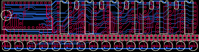
 ShiftPWM Test Board, CAD Files Below |
ShiftPWM uses only 3 signals to drive any number of shift register chips.
| Signal | Teensy 2.0 | Teensy++ 2.0 | Teensy LC & 3.x | 74VHC595 |
|---|---|---|---|---|
| Clock | 1 | 21 | 13 | 11 |
| Data | 2 | 22 | 11 | 14 |
| Latch | 8 | 8 | 8 | 12 |
On Teensy LC, 3.0, 3.1, 3.2, 3.5, 3.6, SHIFTPWM_NOSPI must be defined. See the examples in File > Examples > ShiftPWM for details.
Example Program
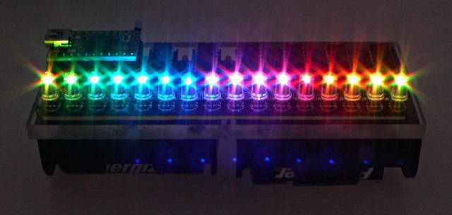
The example code can be opened from the menu:File > Examples > ShiftPWM > ShiftPWM_RGB_Example
CPU & On-Chip Resource Usage
ShifPWM uses timer1 and the SPI port to rapidly shift new data to all the pins. This consumes a large amount of CPU time. The ShiftPWM.PrintInterruptLoad() function gives information about how much CPU time is used.ShifPWM lets you configure the number of 8 bit registers, and the number of PWM levels. As more registers are used and more levels are supported, more data must be shifted, which slows the refresh rate. These settings should be adjusted to for a good, flicker-free refresh rate.
Test Circuit Board
These Circuit Board CAD Files were fabricated by Laen's PCB Group Order.