X10 Library
X10 allows you to send control messages to X10-based AC power line control devices.
| Download: |
Included with the Teensyduino Installer |
This library supports transmit-only communication. Receiving status and 2-way communication is not available.
Hardware Requirements
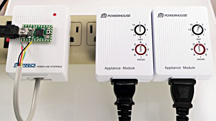
You will need a PSC04 (pdf) or similar X10 powerline interface.

|
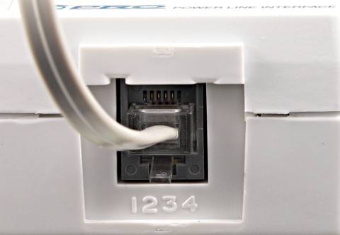
Connecting the PSC04 is easy, using a RJ-11 connector (same a telephone). The
center two wires are ground, and the other 2 just connect any pins.
Pin details below.
Basic Usage
x10 myHouse = x10(zeroCrossPin, dataPin);Create the x10 object with a name of your choice, using the 2 pins where you connected the signals. While you could create multiple x10 objects, in practice there's no reason to do so unless you have completely separate electrical systems! A single X10 transmitter will send to all X10 devices attached to the same AC power line.
myHouse.write(house, unit, numTimes);
Select a specific X10 device to receive communication.
house may be A, B, C, D, E, F, G, H, I, J, K, L, M, N, O, or P.
unit may be UNIT_1, UNIT_2, UNIT_3, UNIT_4, UNIT_5, UNIT_6, UNIT_7, UNIT_8, UNIT_9, UNIT_10, UNIT_11, UNIT_12, UNIT_13, UNIT_14, UNIT_15, or UNIT_16
numTimes specifies the number of times to send this message.
myHouse.write(house, function, numTimes);
Send a command to a X10 device
house may be A, B, C, D, E, F, G, H, I, J, K, L, M, N, O, or P.
function may be ALL_UNITS_OFF, ALL_LIGHTS_ON, ON, OFF, DIM, BRIGHT, ALL_LIGHTS_OFF, EXTENDED_CODE, HAIL_REQUEST, HAIL_ACKNOWLEDGE, PRE_SET_DIM, EXTENDED_DATA, STATUS_ON, STATUS_OFF, or STATUS_REQUEST. Functions which affect a single unit will control the unit previously selected with above write using UNIT_X. Some of these functions involve 2-way communication, which can't be used with this x10 library that only supports transmitting.
numTimes specifies the number of times to send this message.
Normally messages only need to be sent once, but numTimes may be set to 3 if you suspect noise or interference may be corrupting some of your messages.Example Program
#include <x10.h>
#include <x10constants.h>

const int zeroCrossPin = 2;
const int dataPin      = 3;

// set up a new x10 instance:
x10 myHouse =  x10(zeroCrossPin, dataPin);

void setup() {
  Serial.begin(9600);
}

void loop() {
  Serial.println("Lights on:");
  myHouse.write(A, UNIT_1, 3);
  myHouse.write(A, ON, 3);
  delay(1000);

  Serial.println("Lights off:");
  myHouse.write(A, UNIT_1, 3);
  myHouse.write(A, OFF, 3);
  delay(1000);
}
Connector Pinout & Wiring

PSC04 Power Line Interface |
| PSC04 Pin | Signal |
|---|---|
| 1 | Zero Crossing Detect |
| 2 | Ground |
| 3 | Ground |
| 4 | Data |
When the Zero Crossing Detect signal should be connected to a pullup resistor (the libary enables the built-in pullup), the signal should have a 60 Hz square wave. If measured with a voltmeter in DC mode, it should measure approximately 2.5 volts, or half of the power supply voltage.
Version 0.4
Version 0.4 enables the built-in pullup resistor. Prior versions of this library required you to connect a resistor, but with 0.4 you may just connect the Zero Crossing signal directly to any pin.Other minor improvements in code efficiency were also added in 0.4.