|
|
| ||
|
Shopping Cart
|
| Home | Products | Teensy | Blog | Forum |
|
You are here:
MP3 Player
|
|
|
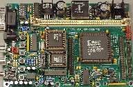
Schematic DiagramsThese schematics are one of three parts needed to build the entire MP3 player. The other two are the 8051 Development Board and IDE Interface.Disclaimer: This design data is distributed in the hope that it will be useful, but without any warranty; without even the implied warranty of merchantability or fitness for a particular purpose. Matthew Burnham reported that hy built the circuits shown in this schematic and got it to work. This diagram was drawn after I built the player, bit it looks like it's probably correct.
It's a good idea to avoid placing the MAS3507D chip in its socket until the 3 volt power supply has been verified. The decoder chip is expensive and it probably will be damaged if 5 volts is applied.
The crystal oscillator shown is 14.7456 MHz. It is a 3 volt low power type (TODO, get manufacture part number here). If you are very concerned about sound quality, you may want to add more power supply bypassing to the D/A converter, perhaps with ferrite beads or inductors. The CS4327 chip is supposed to be used with a low-pass filter on its outputs. I didn't build this on my first board, but I will add it to my next design. The CS4327 data sheet has some good suggestions about what to do for a low-pass filter.
The pushbuttons are very simple, and the 8051's port pins provide the pullup resistors, so all that is necessary is to connect the three buttons. They must be normally open momentary contact types. The firmware contains some code to avoid de-bounce the signals.
This last circuit is optional, but if it is not used, whatever signal would normally drive the 8051's RXD pin must not be connected. When the firmware uses the 8051's serial port in mode 0, both TXD and RXD become output signals. This tri-state buffer just disconnects the normal receive signal from the RS-232 interface, so that there won't be a logic conflict between the 8051 and the normal receive signal.
Update, July 22, 2001:
|