|
|
| ||
|
Shopping Cart
|
| Home | Products | Teensy | Blog | Forum |
|
You are here:
MP3 Player
|
|
|
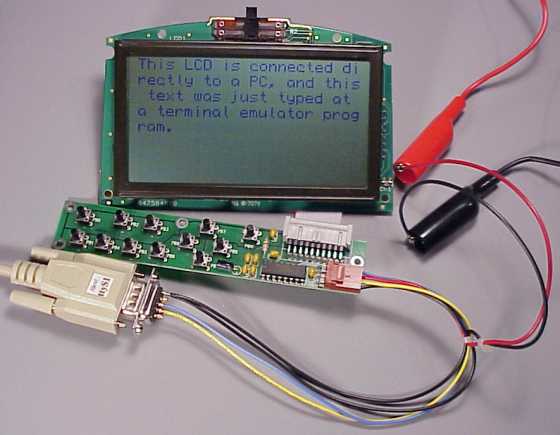
Pushbutton Board For LCD DisplayPJRC discontinued this product in February 2009, and has not sold these LCDs since that time. PJRC has never sold this LCD via eBay.This pushbutton adaptor board connects the JW-002 Display to the MP3 player. An EPROM or Flash ROM, programmed with LCD.HEX, must be placed in the firmware socket on the JW-002 display board. LCD.HEX is built from JW002.ASM and four font description files, which are distributed within the source code on the firmware download page. A ready to use display package is available from PJRC. This package includes the JW-002 display with a properly programmed firmware chip installed, the assembled pushbutton adaptor board, a ribbon cable to connect the JW-002 to this pushbutton board, and a 4 pin cable to connect the pushbutton board to the MP3 player. The information on this page is intended for those who want to understand how the pushbutton board works, make modifications, or build their own. A MAX232 chip converts the serial port signal polarity and levels. The negative voltage generated by the MAX232 charge pump is used to drive the LCD's -Vee input. Twelve pushbuttons are connected in a 4x3 matrix and are scanned by the firmware running on the display. A simple R-C delay provides a reset signal to the reset circuitry on the JW-002 display. Schematic Diagram Parts List
Circuit Board Layout Artwork
Component Placement About the JW-002 DisplayThe JW-002 display was originally used in an AT&T terminal of some sort, and many more displays were made than were ultimately used. These displays are available as a surplus item from Earth Computer Tech. They have a page with more information about this display, including a pinout of the 17 pin connector.The JW-002 firmware socket is wired for the standard 32 pin pinout (not the 28 pin arrangement found on a 27C512 chip), so only chips which use the 32 pin pinout will work in the socket. PJRC does not have a schematic for the JW-002 display. Some information about the circuitry, discovered by reverse engineering, can be found in the comments of JW002.ASM within the firmware source code. If you wish to develop your own applications using this display, that source code is all the information that PJRC can provide for you. Be sure to download the latest code from CVS, as older versions had bugs due to minor misunderstanding from incomplete information in the initial round of reverse engineering. Earth's web page has a "Coming Soon" section, where a schematic and other detailed information may someday appear. Earth may have had an engineer begin a reverse engineering effort at one time, but when we contacted them early in 2001, they had no information. All of the code in JW002.ASM was written based on reverse engineering done by Paul Stoffregen/PJRC and has been tested on many display boards (but of course the code comes with no warrant, just like all other software, free or expensive alike). We have shared our source code with Earth, and it is available for you to download and use as well.
 Using A Raw JW-002 From Earth LCD (not from PJRC)A few times the question has come up, how to use a raw JW-002 LCD (not purchased from PJRC). Here's a brief answer, adapted from an email message.
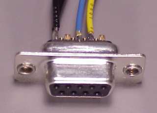
> Hi guys, i got 2 of those LCDs from a friend of mine who This would be a lot easier with a display kit purchased from PJRC, which comes with the correct firmware installed on the display, a working pushbutton board, and the two cables needed. The PJRC display comes with a 4-pin plug that mates with the MP3 player, but it is easy to use with a PC instead of the MP3 player, as described above. But with a raw display, the firmware chip that comes installed is useless and you must replace it with one that has the LCD.HEX firmware (that PJRC provides as a free download including source code, even though you purchased the LCD elsewhere!) You will need to program a flash rom or EPROM with LCD.HEX and replace the socketed chip that came with the board. You will need an EPROM programmer, and the correct DIP-PLCC socket adaptor to hold the chip while it is in the programmer (beware, the common 32-to-28 pin adaptor will not work, you need 32-to-32). The socket is wired for a 32 pin flash rom pinout, not the 28-pin 27Cxxx eproms that have 4 unconnected pins when purchased in 32 pin PLCC. I use the 39SF512 chip in the displays from PJRC.
Update: now you can buy a pre-programmed firmware chip. PJRC provides these chips to allow you to make use of your JW-002 LCD (purchased from a third party), but PJRC does not provide the pushbutton board and custom ribbon cable separately for use with LCD purchased elsewhere. This step is absolutely required. If you don't have an EPROM programmer, you must borrow or buy one, or find someone who has one to program the chips for you. No matter how badly you want those displays to work, you're not going to get far with the original chip that comes installed with AT&T's old firmware. The display does not care if you have access to an EPROM programmer or not. If you can't get a chip with LCD.HEX installed, you might as well just give up and throw the display in the trash. Once you've got workable firmware on the display, then all you really need to do is apply power and use a chip like the MAX232 to convert the RS-232 signals from your PC to the TTL levels needed on the display. The MAX232 can also be used to provide -Vee, so you only need a single +5 volt power supply. The pushbuttons are optional. I put a complete schematic and layout for the pushbutton board on the web, so you can use it: To make something display from the PC, you could just run hyperterminal and set it to 19200 baud. Anything you type will (should, if you've done everything correctly) immediately appear on the display. You can type the control command (they all begin with a backslash '\' ) to do special things like position the cursor, change fonts, etc.
>I thought i can just make the board (the one with the buttons) You don't need to learn any ASM... but you absolutely MUST replace the firmware chip that came with the display with one that has LCD.HEX (which is written in assembly source, but you can download a compiled LCD.HEX from Dave's nightly build site and not worry about using the assembler at all). If you DO want to learn asm, you could write your own LCD.HEX, using my source code as a guide. There are instructions in the source for a set of mods to the board so it can run PAULMON2, which allows you to download your experimental code into half of the RAM on that board. This is the approach I used to develop LCD.HEX, and Tom used a similarly mod'd board to develop his extensions (marquee horz scroll, double buffered write/update, etc) that are in today's code. Those mods and this sort of code development are not for beginners! |