|
|
Errata for MP3 Player Board Rev A
Though we wanted to bring you a perfect board, there are a
couple errors on the board that require modifications. We're
really sorry about this, but the good news is that the mods
are small, easy to make, and not very messy.
There are also some minor issues that you
should be aware of, that can save you some frustration
when building the board.
Because the board is packed so
tightly (to allow it to fit into the 5.75 by 4 inch size),
there are a number of components that are not properly
marked. These are listed here. Please be careful when
assembling the board, as there are several parts that
look similar, but are in fact quite different. We have
attempted to arrange the assembly steps and our packaging
avoid similar appearance parts within each assembly step.
This errata list applies to MP3 player board, marked
REV A, near the top edge of the 84 pin PLCC socket.
Corrections, Required To Make The Board Work
- Trace Cut, Pin 7 of 74HC165
The trace between the 22k resistor network and pin 7 of the
74HC165 chip must be cut, to allow the CPU to access the
flash rom chip.
- Trace Cut, Pin 15 of 74HC165, jumper to ground
The trace between pins 15 and 16 of the 74HC165 must be cut. Pin 15
then must be connected to ground. We suggest soldering a short wire
between pin 15 and the ground trace that runs under the chip on the
solder side. This ground trace has a via near pin 3. This modification
is required to allow the firmware to read the pushbuttons.
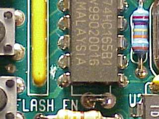
Figure 1: Trace Cut, Pin 7 of 74HC165 |
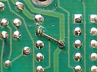
Figure 2: Trace Cut, Pin 15 of 74HC165, Jumper To Ground |
Minor Issues
- IDE Interface Missing Pin 1 Marking
Pin 1 of the IDE interface should be marked on the board.
On both connectors, pin 1 is on the end facing the SIMM.
Pin 1 is labeled on the assembly diagrams.
Now would
be a good time to mark pin #1 on your board with a permanent pen,
to avoid connecting a drive's cable backwards.
- 44 Pin Header, Tight Fit
The 44 pin header
(Step 5) fits tightly. It can be tricky
to insert this part, because the holes are so small. Do not apply
excessive force, the part will press into the board without
excessive force when it is aligned straight.
- 1N4737 Diode, Slight Bend Necessary To Fit SIMM Socket
The 1N4737 diode
(Step 10)
may need to have its legs bend slightly to prevent it from
obstructing the SIMM socket. We suggest that you try to fit
the SIMM socket while this part is in the board but not yet
soldered, to verify that this diode will not prevent you from
correctly inserting the SIMM socket.
General Notes
- 33 pF Capacitors Not Marked
The location of these parts is not marked on the board. Two of these
capacitors are located by each crystal. These parts are included
in Step 2.
- 0.1 µF Capacitors Not Marked
This part is all over the board. The only indication of the location
of the capacitors is an outline around each of the two holes for the
part. There are 15 capacitors in the MP3 player
(Step 4), and 9 in the power supply
(Step 8).
We suggest that you insert the 33 pF capacitors before these,
because it's easy to place one of these where the 33 pF parts belong.
- 22k Resistor Network Not Marked
The location of this part is not indicated on the board. Be very careful,
not only is it directional, but it looks identical to the 4.7k resistor
network. The 22k resistor network is located by the 6 push buttons.
It is marked on the side with 8X-1-223. This side of the part needs to
be facing the push buttons.
This part is included in
Step 2.
- 4.7k Resistor Network Not Marked
Similar to the 22k resistor network, the location of this part is not
indicated on the board. It is located by the 40 and 44 pin connectors.
Be careful, it looks identical to the 22k resistor network. On the side
of this part is the marking 8X-2-472.
This part is included in
Step 3.
- 100 µF Capacitors Not Marked
The location of this part is not indicated on the board. Be very careful,
this part looks almost identical to the 10 µF capacitor. There
are circles on the board indicating that one of the two capacitors
should be inserted. The positive wire is marked for the capacitor.
This part is included in
Step 4 and
Step 10.
- 10 µF Capacitors Not Marked
The location of this part is not indicated on the board. Be very careful,
this part looks almost identical to the 100 µF capacitor. There
are circles on the board indicating that one of the two capacitors
should be inserted. The positive wire is marked for the capacitor.
This part is included in
Step 5 and
Step 9.
- Parts Marked On The Board, But Not Used
There are two parts that are marked on the board, but were subsequently
removed from the design. Be sure NOT to insert any parts into the
following locations:
- A capacitor located between the 44 pin PLCC socket and the SIMM socket
- A 69.8 k resistor located between the 34 pin connector and the SIMM socket
These two parts form a RC reset circuit for the 87C52 CPU, which was
replaced with a MAX810 surface mount IC
(Step 1)
on the solder side under the
CPU. The MAX810 offers better performance. The capacitor can
physically obstruct inserting some SIMMs.
|