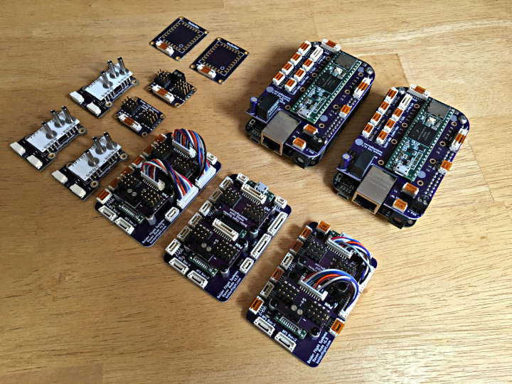
Years ago, in my slow quest for better photography of electronic projects, I built a light table to eliminate shadows. Most of the white background photos you see on the PJRC site are shot with this light table.
This is how it turned out.
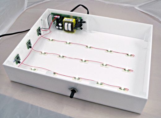
The build used boards from OSH Park (then “Laen’s PCB group order”), materials from TAP Plastics, 15 white LEDs and parts I mostly had laying around.
This view is inside a cheap 2 foot sized light tent I purchased from some ebay vendor, and a couple bright lights outside the tent on both side.
The LEDs are Cree CLM3C-WKW-CWBYA453, which are supposedly the same 5500K color temperature as the CFL lights outside the tent. Maybe that matters, maybe not, but it seemed like a good idea.
The Cree LED is a surface mount part, but fortunately Lean’s PCB group order made it very easy to convert to something I can solder wires onto. All the PCBs mount with double sticky mounting tape.
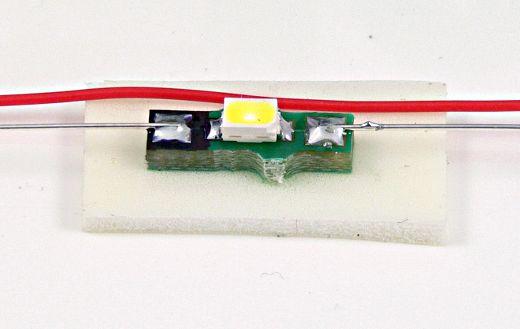
As you can see in this LED photo, there’s a bit of shadow. It’s a soft shadow due to the light tent casting light from many directions, but it’s still very present. This is the type of shadow I’m hoping just a little bit of under side lighting will eliminate.
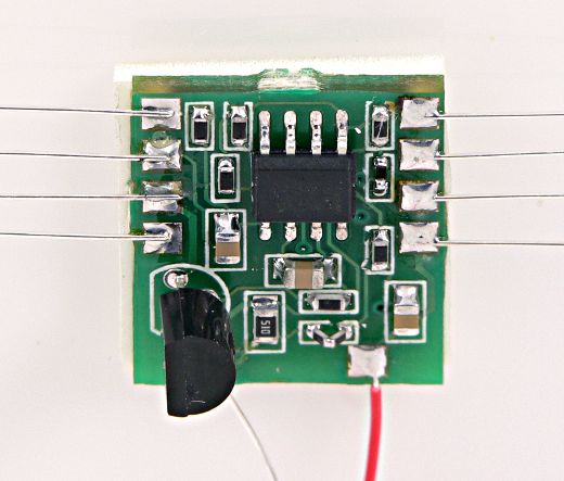
This little board is a constant current regulator. It takes a 0 to 5 volt input and regulates a 0 to 20 mA output current to a string of 5 LEDs. I wanted to make sure the current was perfectly constant since the camera might choose a quick shutter time.
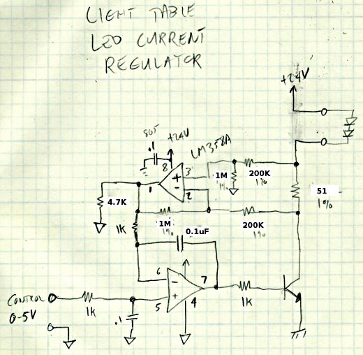
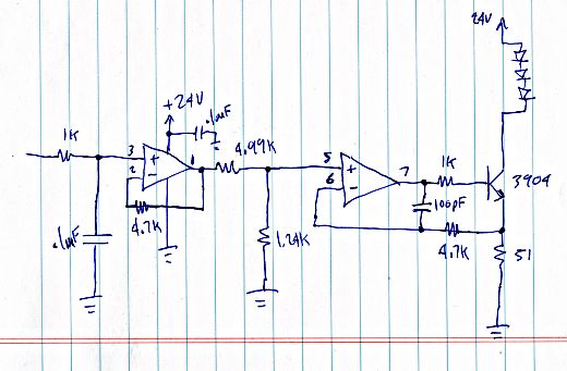
Here’s the schematic for that circuit. At the time, it seemed like a good idea to sense the current using a resistor between the NPN transistor’s collector and the LEDs. The idea was any small change in ground potential between the board 0-5V control signal wouldn’t matter, if I ran separate signal and power ground lines.
But I didn’t consider the current draw though those resistors around the upper opamp. As you can see in the schematic, I change the values to about as high as I reasonably could. It still have a tiny bit of the lowest part of the range where the LEDs won’t completely turn off.
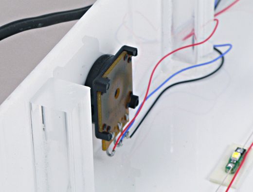
The 0 to 5 volt signal just comes from this potentiometer on the front panel. Because it’s driving only the inputs to opamps, it doesn’t have any substantial load. I still used a 1K pot anyways, though a higher value would have consumed a little less current. I guess I didn’t care about an extra 5 mA.
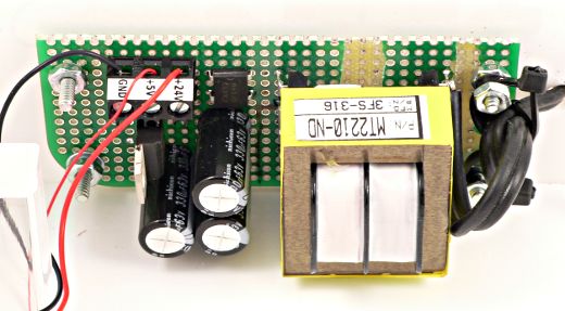
The power for everything comes from this simple little power supply, which is just (approx) 24 volts unregulated, and a 5 volt regulated output from the pot, which is from a 7805 regulator. Simple.
Of course, the opamp circuit isn’t perfect. After putting this together, I decided to try a different approach, sensing on the emitter side, and no current sensing path to add to the LED current! I also included 4.7K resistors on the feedback looks, and the positive inputs see about a 1K impedance. Any errors from the opamp’s input (PNP) bias currents should be small, and should be more on the negative than positive, so hopefully any tiny error will tend to reduce the LED current, not increase.
Then again, the original boards might work out ok, but Laen’s PCB group order makes it so very easy to just quickly draw up a (small) board. Because the cost is so low, it’s easy to just send it off without all the worry the goes into a normal board order.
I still haven’t actually put this thing to use… the top plastic cover turned out to be just a bit too small, so I need to go shave it down to size on my table saw (which currently has a bunch of other project stuff piled on top of it). But soon, with a little luck, I’ll be able to take pictures of electronic stuff and adjust the light table to null out or at least soften away most of the little shadows that I still get, even with the light tent.
Originally this article was published on the DorkbotPDX website. Since that time, the DorkbotPDX blog section has vanished. I’m reposting it here, to preserve this info. A copy of the original can also be found at the internet archive.
