I purchased a cheap USB power pack, thinking it would be ideal for powering small projects. But it automatically shuts off if the device isn’t drawing a lot of power, since it’s meant for charging cell phones.
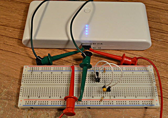
Here’s a 2 transistor circuit that keeps it on with very little battery drain by using brief pulses.
I wish I would have thought of this idea, but it came from this forum post by “Jp3141”. The battery pack automatically turns off if it doesn’t see a high current draw. But drawing a high current for only a brief time is enough to keep its internal timer going.
First, I did some experimenting and found a 22 ohm resistor keeps the power on indefinitely. A 27 ohm resistor kept it on for 19 seconds. With no load, it stays on for only 13 seconds. So a 22 ohm load it is!
Just connecting a 22 ohm resistor to the 5 volt power is a pretty heavy load that would drain the battery. A 22 ohm resistor also burns about 1.1 watts, so it gets HOT. But the load doesn’t need to be on most of the time. The next step was connecting a Teensy and transistor circuit to turn on the load under software control.
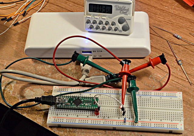
Here the 5V pin drives a LED in series with a NPN base-emitter junction, to apply about 2.3 volts to a 10 ohm resistor. Of course, the NPN transistor has high current gain, so most of the 230 mA that flows through the 10 ohm resistor comes from the battery through the collector.
A little experimenting determined pretty quickly that pulses in the 8 to 10 ms range usually keep the battery pack on, but it sometimes turns off after a couple minutes. 20 ms seems very stable.
Knowing 20 ms is needed, I switched from using the Teensy++ to this simple 2 transistor oscillator:
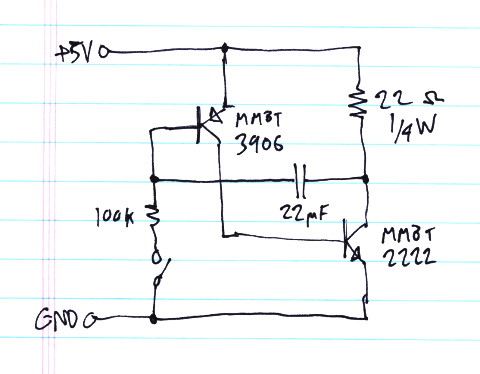
A quick napkin calculation seemed to suggest this would need a really large capacitor. But with a little fiddling, it turned out 22 uF was enough. This circuit creates a pulse slight over 20 ms approximately every 1.4 seconds.
Here’s another close-up of the circuit on the breadboard. Just 2 transistors, 1 capacitor, and 2 resistors.
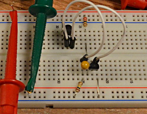
I let this run for about half an hour, with the battery pack happily remaining on the whole time.
The average battery current is ~3.5 mA.
While the transistors are on, the current is approx 222 mA (4.9V on 22 ohms). But the duty cycle is about 1.6%.
Inside the pack, a switching power supply is running to step up the batteries from 3.7 to 5 volts, and it’s powering those 4 blue LEDs. The internal stuff inside the pack probably wastes a lot more than only 3.5 mA.
Of course, then I did a quick PCB layout. I added a switch in series with the 100K resistor, so it can be left plugged in and turned off to allow the battery pack to shut itself off. It’s a tiny board, only about the size of the USB connector itself.
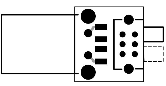
I sent the files in to OSH Park. Here’s their preview.

Here’s the board on their site, if anyone else wants to build this:
http://oshpark.com/shared_projects/Da8m8oAz
The 5 parts are on the bottom side of the PCB. Here’s a placement diagram:
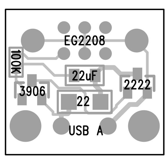
Here’s a list of part numbers:
 1276-5649-1-ND        22 ohm resistor, 1/4 watt
 490-1719-1-ND         22 uF capacitor, X5R, 6.3V
 RMCF0603FT100KCT-ND   100K resistor
 MMBT2222A-FDICT-ND    NPN Transistor
 MMBT3906-FDICT-ND     PNP Transistor
 WM17118-ND            USB Connector
 EG1941-ND             Switch
If you need to tune the timing for a different battery pack, increasing the capacitor makes the pulse wider and lengthens the time between pulses. Decreasing the 100K resistor makes the pulse occur more frequently, without changing the width of the pulse.
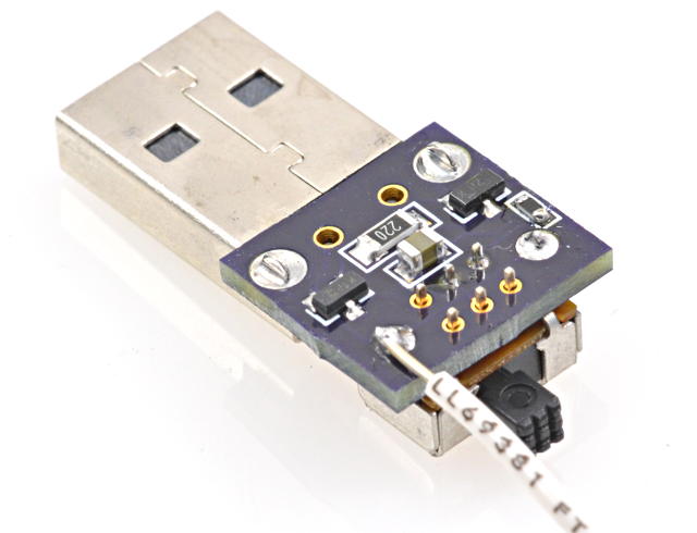
EDIT: My battery pack turned off a couple times times after many minutes. I increased the capacitor to 47 uF and it ran for an hour. 22 uF might be a little on the low side? If you build this circuit, a little tweaking on the capacitor or resistor values might be needed if your battery pack is different.
EDIT AGAIN: Later I purchased an identical-looking battery pack, except it had black plastic instead of white. It turned out to have a completely different power detecting scheme. The pulses wouldn’t work. This little circuit clearly doesn’t apply to every battery pack, but it worked very well on the earlier white one.
This article was originally published on the DorkbotPDX website, on November 5, 2013. In late 2018, DorkbotPDX removed its blog section. An archive of the original article is still available on the Internet Archive. I am republishing this article here, so anyone still using these battery packs can try this circuit.