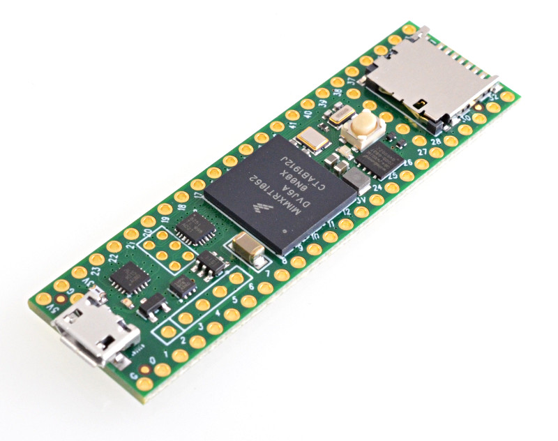
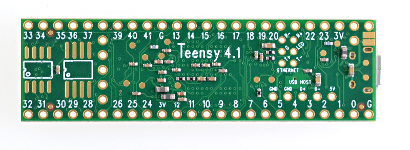
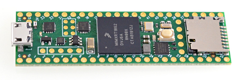
Teensy 4.1 is now available with access more I/O and memory expansion.
Teensy 4.1 features a 10/100 Mbit Ethernet PHY.
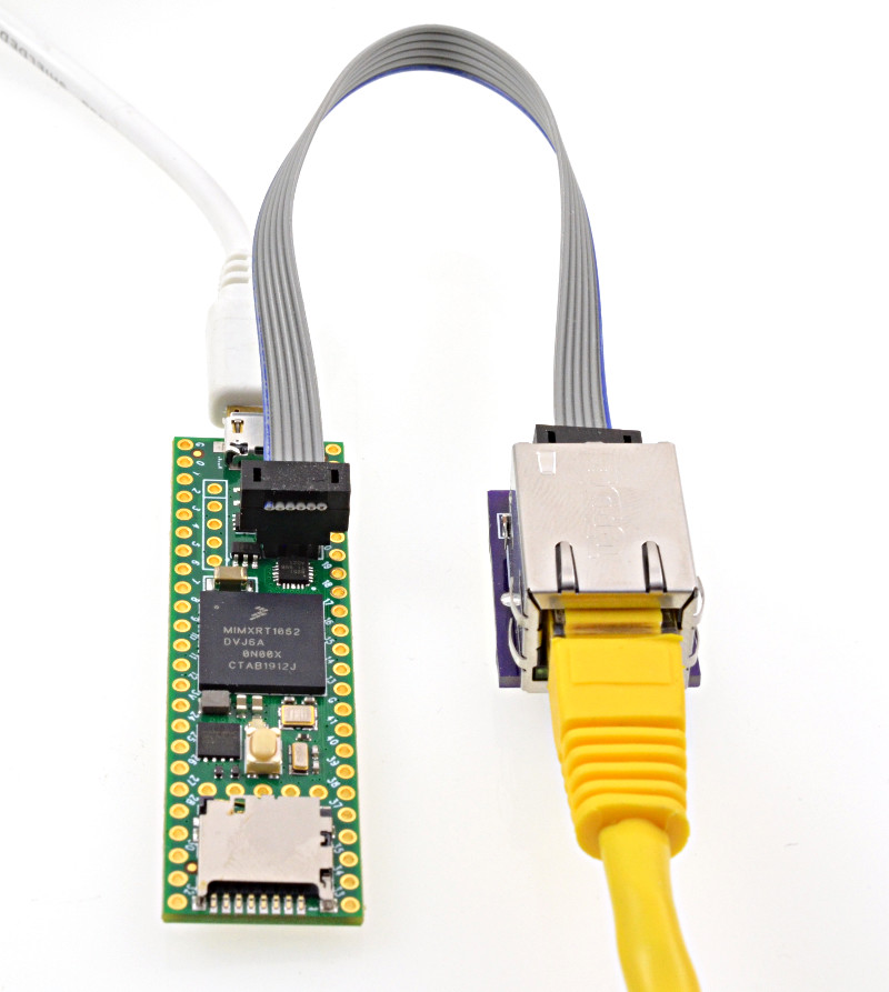
The Ethernet port also has IEEE1588 precision packet timestamping.
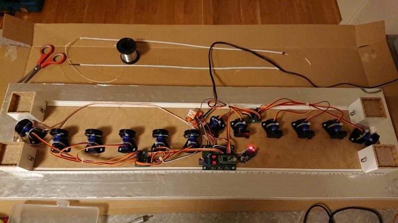
Fast Ethernet opens up possibility for low latency & high bandwidth Artnet LED projects, streaming audio, open sound control and other Ethernet-based protocols that were difficult to accomplish with a traditional SPI-based Ethernet shield. Traditionally use of Ethernet in a project has involved a choice of single board computers with high bandwidth Ethernet using systems not designed for low latency tasks, versus microcontrollers designed for real-time tasks but with slow Ethernet or lacking performance to handle Ethernet’s speed. Teensy 4.1 with a Cortex-M7 processor at 600 MHz opens up the possibility to use the high bandwidth and low latency of Ethernet on a microcontroller designed for real-time tasks.
Teensy 4.1 includes a USB host port, supporting 480 Mbit/sec high speed USB. While Teensy 4.0 has those USB host data signals on surface mount pads, Teensy 4.1 adds the hot-plugging power management needed to simply connect a USB host cable and be able to plug in a USB device. Or a USB hubs can be used to connect many USB devices.
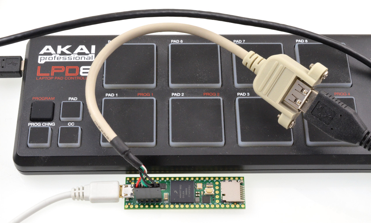
USB devices are supported by the USBHost_t36 library, which is installed into the Arduino IDE automatically by the Teensyduino installer.
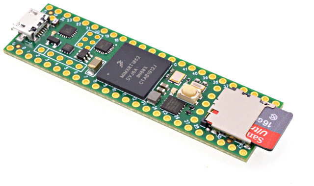
Another feature technically present on Teensy 4.0, but difficult to use, is native SDIO for fast data transfer to a SD card. Teensy 4.1 includes the SD socket, so you can easily use a micro SD card with the card’s native SDIO protocol rather than slow SPI access.
Teensy 4.1 also includes locations to solder additional memory chips. The larger space is meant for a QSPI flash memory and the smaller space is intended for a 8MB PSRAM chip.
The IMXRT1062 microcontroller on Teensy 4.0 and 4.1 has 1MB of RAM built in. For many real-time control projects, the internal RAM is plenty. But some projects can greatly benefit from the added memory. Frame buffers for high resolution TFT displays are the most common use, allowing advanced graphics rendering. Large memory is also very useful for special audio effects like advanced reverb, buffering fast incoming data before logging to a SD card, and for emulation of retro computer systems like classic arcade games.
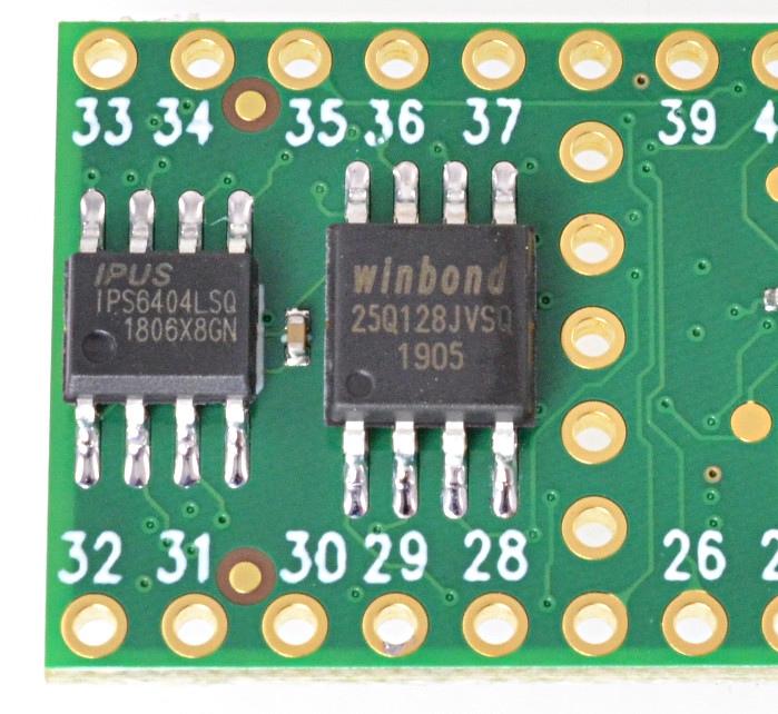
These extra memory chips have a dedicated QSPI bus, which is independent from Teensy 4.1’s main program memory. When a flash memory chip added for storage of files or other data, this dedicated bus means it does not interfere with normal program memory access. This is especially valuable while writing data or erasing sectors in the extra flash memory. For real time projects controller motors, synthesizing or processing real-time audio, communicating high speed data or other tasks requiring low latency, flash writing can be done to the extra flash chip without blocking access to the normal program memory.
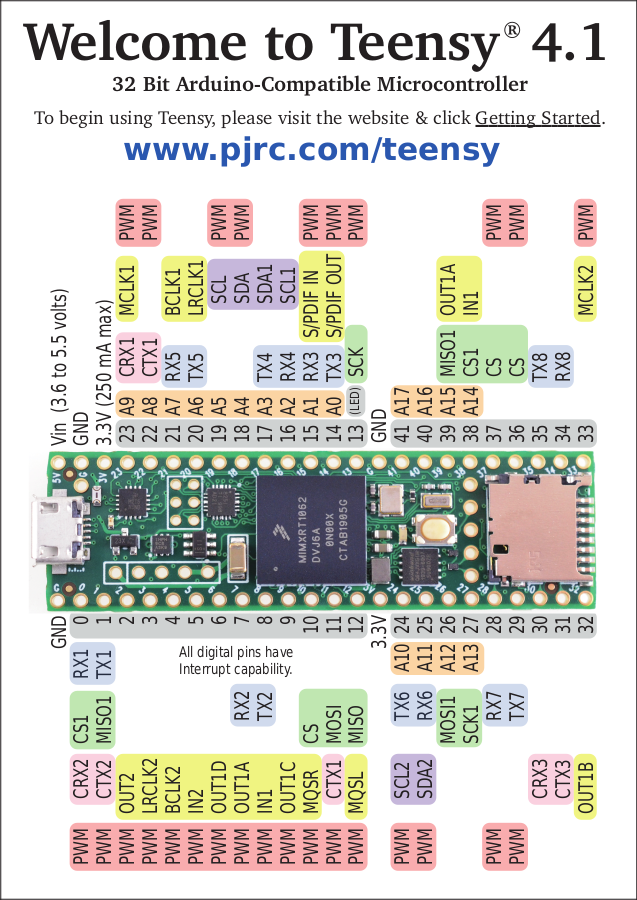
Teensy 4.1’s larger form factor also bring more I/O pins, and makes the difficult-to-access bottom pads from Teensy 4.0 very easy to access, breadboard-friendly pins. The new I/O pins bring an 8th serial port, more analog inputs and PWM outputs, and access to 16 contiguous native port pins, useful for projects needing fast parallel I/O.
Not every project requires so much I/O or extra memory. Teensy 4.0 fills those needs. But when you do need more I/O, more memory, fast Ethernet, or connecting USB devices or fast SD card access, the larger Teensy 4.1 brings this extra I/O capability to a platform designed for real-time use with fast 600 MHz M7 performance.