Blog Posts

PinSim – Virtual Reality Pinball Machine

Jeremy Williams built PinSim, a cabinet controller for virtual reality pinball to get much more realistic game playing experience.

Jeremy, a huge pinball enthusiast, knew he had to build a cabinet when he saw Pinball FX 2 VR at Oculus Days.  Digital pinball games have been around for quite a while, but as Jeremy noted, one of the problems with them is that your perspective is static.  Virtual reality (VR) pinball games allows users to change their perspective while playing, allowing for more finesse.

The PinSim cabinet improves the game play experience by adding a few elements that are crucial for realistic pinball play such as tactile controls, “non-clicky” buttons for the flippers, and an accelerometer-based nudge system.  Not only can you nudge the cabinet to move the ball, but if you nudge too much, you’ll tilt.

For the electronics a Teensy-LC using the MSF-XINPUT library by Zack Littell is used to emulate an Xbox 360 gamepad.

Build instructions for the cabinet can be found over on Tested.  Code for the project can be found on GitHub.  Over on the forum there’s a thread helping a user get all the libraries need to compile the PinSim code.


Battery Pack Load

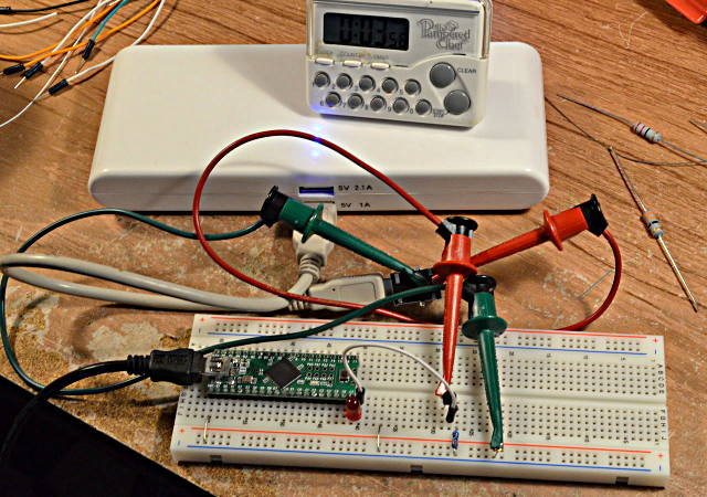
I purchased a cheap USB power pack, thinking it would be ideal for powering small projects.  But it automatically shuts off if the device isn’t drawing a lot of power, since it’s meant for charging cell phones.

Here’s a 2 transistor circuit that keeps it on with very little battery drain by using brief pulses.

I wish I would have thought of this idea, but it came from this forum post by “Jp3141”.  The battery pack automatically turns off if it doesn’t see a high current draw.  But drawing a high current for only a brief time is enough to keep its internal timer going.

First, I did some experimenting and found a 22 ohm resistor keeps the power on indefinitely.  A 27 ohm resistor kept it on for 19 seconds.  With no load, it stays on for only 13 seconds.  So a 22 ohm load it is!

Just connecting a 22 ohm resistor to the 5 volt power is a pretty heavy load that would drain the battery.  A 22 ohm resistor also burns about 1.1 watts, so it gets HOT.  But the load doesn’t need to be on most of the time.  The next step was connecting a Teensy and transistor circuit to turn on the load under software control.

Here the 5V pin drives a LED in series with a NPN base-emitter junction, to apply about 2.3 volts to a 10 ohm resistor.  Of course, the NPN transistor has high current gain, so most of the 230 mA that flows through the 10 ohm resistor comes from the battery through the collector.

A little experimenting determined pretty quickly that pulses in the 8 to 10 ms range usually keep the battery pack on, but it sometimes turns off after a couple minutes.  20 ms seems very stable.

Knowing 20 ms is needed, I switched from using the Teensy++ to this simple 2 transistor oscillator:

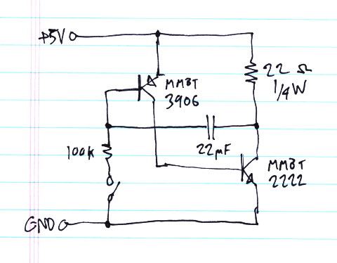
A quick napkin calculation seemed to suggest this would need a really large capacitor.  But with a little fiddling, it turned out 22 uF was enough.  This circuit creates a pulse slight over 20 ms approximately every 1.4 seconds.

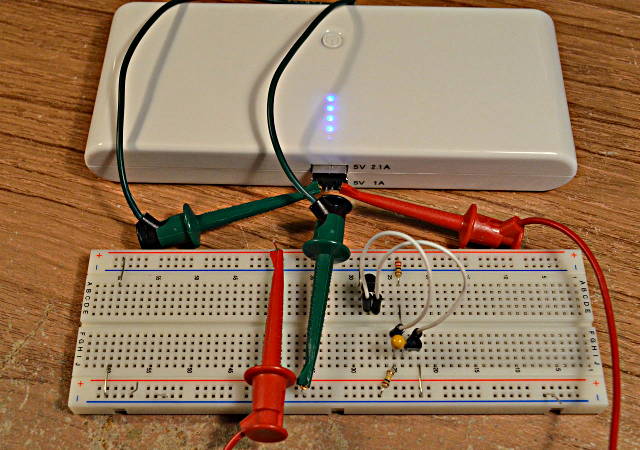
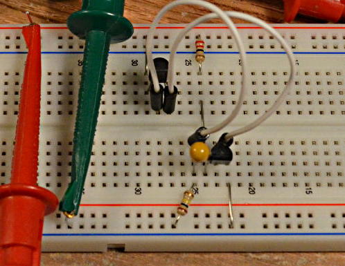
Here’s another close-up of the circuit on the breadboard.  Just 2 transistors, 1 capacitor, and 2 resistors.


I let this run for about half an hour, with the battery pack happily remaining on the whole time.

The average battery current is ~3.5 mA.

While the transistors are on, the current is approx 222 mA (4.9V on 22 ohms).  But the duty cycle is about 1.6%.

Inside the pack, a switching power supply is running to step up the batteries from 3.7 to 5 volts, and it’s powering those 4 blue LEDs.  The internal stuff inside the pack probably wastes a lot more than only 3.5 mA.

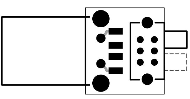
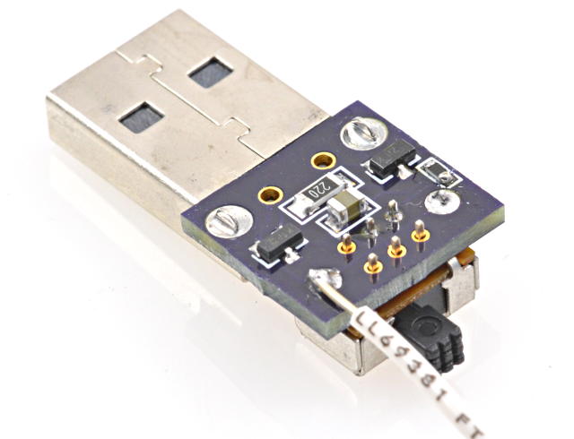
Of course, then I did a quick PCB layout.  I added a switch in series with the 100K resistor, so it can be left plugged in and turned off to allow the battery pack to shut itself off.  It’s a tiny board, only about the size of the USB connector itself.

I sent the files in to OSH Park.  Here’s their preview.

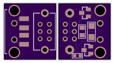
Here’s the board on their site, if anyone else wants to build this:

http://oshpark.com/shared_projects/Da8m8oAz

The 5 parts are on the bottom side of the PCB.  Here’s a placement diagram:


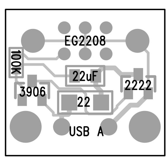
Here’s a list of part numbers:

 1276-5649-1-ND        22 ohm resistor, 1/4 watt
 490-1719-1-ND         22 uF capacitor, X5R, 6.3V
 RMCF0603FT100KCT-ND   100K resistor
 MMBT2222A-FDICT-ND    NPN Transistor
 MMBT3906-FDICT-ND     PNP Transistor
 WM17118-ND            USB Connector
 EG1941-ND             Switch

If you need to tune the timing for a different battery pack, increasing the capacitor makes the pulse wider and lengthens the time between pulses.  Decreasing the 100K resistor makes the pulse occur more frequently, without changing the width of the pulse.


EDIT: My battery pack turned off a couple times times after many minutes.  I increased the capacitor to 47 uF and it ran for an hour.  22 uF might be a little on the low side?  If you build this circuit, a little tweaking on the capacitor or resistor values might be needed if your battery pack is different.

EDIT AGAIN: Later I purchased an identical-looking battery pack, except it had black plastic instead of white.  It turned out to have a completely different power detecting scheme.  The pulses wouldn’t work.  This little circuit clearly doesn’t apply to every battery pack, but it worked very well on the earlier white one.


This article was originally published on the DorkbotPDX website, on November 5, 2013.  In late 2018, DorkbotPDX removed its blog section.  An archive of the original article is still available on the Internet Archive.  I am republishing this article here, so anyone still using these battery packs can try this circuit.

Yet Another GPS Alarm Clock

Edward Ringel as built Yet Another GPS Alarm Clock that does quite a lot more than tell time.

An alarm clock with everything!  Has a high accuracy temperature compensated clock (DS3231), automatic sync to GPS time, large touchscreen user interface, handling of time zones and daylight savings time.

Code and schematics for the project are available on the ElektorLabs project page, but it looks like you will have to create an Elektor account to access them.


TiSi Box – X-Plane Flight Sim Addon

Hubert (forum user inovasim.de) has created the TiSi Box, a hardware add on to X-Plane that allows for a new kind of visual control.

The TiSi-box combines the nose wheel steering with the sight control using a self-centering rotary knob.  It interfaces with the X-Plane flight simulation software though a Teensy 3.2.

The TiSi-Box will available on the iNOVASim website.

Laser Harp

Johan Berglund built a very cool 16-note, multi-scale laser harp.

This impressive build features 16 beams, MIDI over USB and 5-pin DIN, adjustable octave and transposition, and and extensive list of  selectable scales.

This project page offers detailed information on how to build your own as well as schematics.  The code is available on GitHub.

ImportWorld – 3D Scanner

FilleK built a 3D scanner using a webcam and a couple of line lasers.

The scanner works by setting an object on a rotary table and a Logitech C920 webcam to capture images of it to a computer over USB.  All the hardware (except for the webcam) is controlled by a Teensy.

Super Otamatone

Evan is working on upgrading his Otamatone by replacing the internal analog synthesizer with a digital synth.

Using a Teensy 3.2 paired with an audio shield, the project aims to put a digital synth in an Otamatone that will include presets that can be configured on the fly.  This could be very useful in making the instrument a bit easier to play.  After all, the world needs a better Otamatone.

Code for the project can be found on GitHub.


El Wire Color Changing

Years ago I experimented with shifting the color of El Wire by changing the AC frequency.

The color effect is subtle, but can be seen by most people with good color vision.

Not long after I published this video, I discovered “dcroy” built this same thing a few months before I did, and using only a 555 timer! Looks like it’s not as unique as I thought!

This is the schematic for the circuit I built.  Most of the parts are small surface mount and they’re hidden under the transformer.

Here’s the code from the Arduino IDE. Pretty simple stuff. But beware, if you try this, it’s essential to drive each transistor for the same length of time, and not more than about 1ms. If you drive one more than the other, or leave either on too long, the transform sees a DC or low frequency signal. That could result in far too much current, probably destroying the transistors if the battery is fresh.

const int pin1 = 12;
const int pin2 = 19;

void setup() {
  Serial.end();  // USB off, to save power
  for (byte i=0; i<25; i++) {
    pinMode(i, OUTPUT);    // all unused pins low
    digitalWrite(i, LOW);  // to avoid wasting power
  }
  pinMode(pin1, OUTPUT);
  pinMode(pin2, OUTPUT);
}

unsigned int us = 250 * 64;
const int usMax = 500 * 32;
const int usMin = 120 * 32;
byte dir = 0;

void loop() {
  digitalWrite(pin1, HIGH);
  delayMicroseconds(us / 32);
  digitalWrite(pin1, LOW);
  if (dir) {
    us = us + 1 + us / 2048;
    if (us >= usMax) dir = 0;
  } else {
    us = us - 1 - us / 2048;
    if (us <= usMin) dir = 1; 
  }
  digitalWrite(pin2, HIGH);
  delayMicroseconds(us / 32);
  digitalWrite(pin2, LOW);
}

This article was originally published on the DorkbotPDX website, on July 12, 2011.  In late 2018, DorkbotPDX removed its blog section.  An archive of the original article is still available on the Internet Archive.  I am republishing this article here, in case anyone might wish to try El Wire color changing.  Admittedly, El Wire became less popular around 2013 when inexpensive LED strips appeared on the market, but it still offers interesting effects which are hard to accomplish with LEDs.


Ambilight with FastLED

David Henderson and his brothers installed their own ambilight on the back of their new TV and the end result looks awesome.

Ambilight is a technology by Philips that uses LEDs mounted on the back of their TVs to add ambient light.  David retrofitted his TV using a total of 100 addressable LEDs.  The project uses a Teensy 3.2 and takes advantage of the FastLED library.

Check out the Instructables page for details on how you can build your own.

Code for the project is also available on GitHub.