Blog Posts

Control Voltage to 1.2V Analog Input Pin

Often the question is asked, what is the simplest way to get modular synth control voltage (CV) into an analog input pin?

This simple circuit using only 3 resistors and 1 capacitor converts the -5V to +5V CV signal range to the 0 to 1.2V ADC input range.

For Teensy 3.2, 3.5 and 3.6, you would use analogReference(INTERNAL) to configure for the 0 to 1.2V range.  Then you can read the CV signal at any time with analogRead().

While this circuit is the simplest and easiest way, it is not necessarily the best way.  The input impedance, or load placed on the CV signal, it 31K ohms, rather than the standard 100K impedance normally used for modular synthesis systems.  This forum discussion goes into the circuit’s limitations and suggests more advanced ways using opamps.


Originally this article was published on the DorkbotPDX website.  Since that time, the DorkbotPDX blog section has vanished.  I’m reposting it here, to preserve this info.  A copy of the original can also be found at the internet archive.

PWM Tutorial by Bolder Flight

Brian Taylor of Bolder Flight has put together a great tutorial on Pulse Width Modulation (PWM).

PWM is commonly used to control servos and electronic speed controllers (ESC) and is useful for many projects.  This tutorial explains PWM and introduces how to wire up and command a servo  Part 2 of the tutorial go over reading PWM commands.

The tutorial features the PWM Backback by Bolder Flight.  This handy backbpack makes it easy to hookup RC Servo Motors to your Teensy.  It features 8 channels of 16 bit PWM output; bused ground, power, and standard servo connectors; and option SBUS communication input.

NDLR – MIDI Sequenced Apreggiator

Darryl McGee and Steve Barile of Conductive Labs have developed the NDLR (pronounced Noodler), a 4-part poly sequenced arpeggiator, chord and drone player based on the Teensy 3.2.

The guys at Conductive Labs came with a unique solution to break down music theory into knobs and controls. The NDLR has four parts that can play up to 8 synths.  The PAD part is a chord player.  Press one of the 7 chord buttons and all the other parts change notes to match.  There are also 2 “Motifs” which are sequenced arpeggiators.  The Drone part can play a single continuous note like a traditional drone does… or choose from various retrigging options, such as having the note retrigger on a chord change, the down beat, every beat, up beat, etc.

Among the many advanced features packed into the NDLR is a pattern and rhythm editor that lets you create custom arpeggios.  You can also save your patches and settings for later recall with the 8 global slave slots, 20 user patter slots, and 20 user rhythm slots.

You can get a NDLR through their IndiGoGo campaign

This video is of a performance by Graig Anthony Perkins using the NDLR.

Light Table For Web White Background Photos

Years ago, in my slow quest for better photography of electronic projects, I built a light table to eliminate shadows.  Most of the white background photos you see on the PJRC site are shot with this light table.

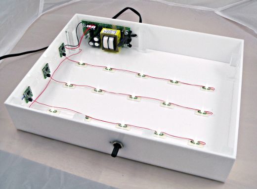
This is how it turned out.

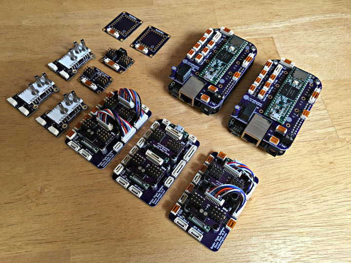
The build used boards from OSH Park (then “Laen’s PCB group order”), materials from TAP Plastics, 15 white LEDs and parts I mostly had laying around.

This view is inside a cheap 2 foot sized light tent I purchased from some ebay vendor, and a couple bright lights outside the tent on both side.

The LEDs are Cree CLM3C-WKW-CWBYA453, which are supposedly the same 5500K color temperature as the CFL lights outside the tent. Maybe that matters, maybe not, but it seemed like a good idea.

The Cree LED is a surface mount part, but fortunately Lean’s PCB group order made it very easy to convert to something I can solder wires onto. All the PCBs mount with double sticky mounting tape.

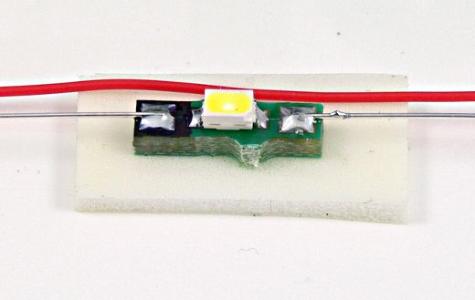
As you can see in this LED photo, there’s a bit of shadow. It’s a soft shadow due to the light tent casting light from many directions, but it’s still very present.  This is the type of shadow I’m hoping just a little bit of under side lighting will eliminate.

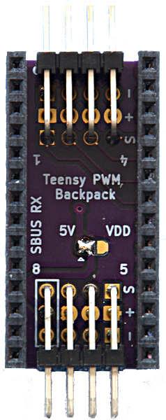
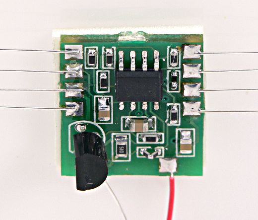
This little board is a constant current regulator. It takes a 0 to 5 volt input and regulates a 0 to 20 mA output current to a string of 5 LEDs. I wanted to make sure the current was perfectly constant since the camera might choose a quick shutter time.

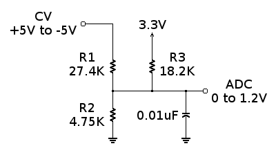
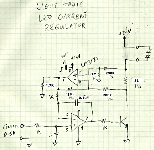
Here’s the schematic for that circuit. At the time, it seemed like a good idea to sense the current using a resistor between the NPN transistor’s collector and the LEDs. The idea was any small change in ground potential between the board 0-5V control signal wouldn’t matter, if I ran separate signal and power ground lines.

But I didn’t consider the current draw though those resistors around the upper opamp. As you can see in the schematic, I change the values to about as high as I reasonably could. It still have a tiny bit of the lowest part of the range where the LEDs won’t completely turn off.

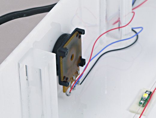
The 0 to 5 volt signal just comes from this potentiometer on the front panel.  Because it’s driving only the inputs to opamps, it doesn’t have any substantial load.  I still used a 1K pot anyways, though a higher value would have consumed a little less current.  I guess I didn’t care about an extra 5 mA.

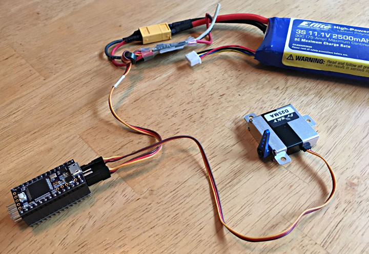
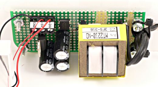
The power for everything comes from this simple little power supply, which is just (approx) 24 volts unregulated, and a 5 volt regulated output from the pot, which is from a 7805 regulator.  Simple.

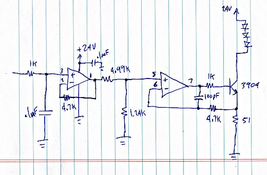
Of course, the opamp circuit isn’t perfect. After putting this together, I decided to try a different approach, sensing on the emitter side, and no current sensing path to add to the LED current! I also included 4.7K resistors on the feedback looks, and the positive inputs see about a 1K impedance. Any errors from the opamp’s input (PNP) bias currents should be small, and should be more on the negative than positive, so hopefully any tiny error will tend to reduce the LED current, not increase.

Then again, the original boards might work out ok, but Laen’s PCB group order makes it so very easy to just quickly draw up a (small) board.  Because the cost is so low, it’s easy to just send it off without all the worry the goes into a normal board order.

I still haven’t actually put this thing to use… the top plastic cover turned out to be just a bit too small, so I need to go shave it down to size on my table saw (which currently has a bunch of other project stuff piled on top of it). But soon, with a little luck, I’ll be able to take pictures of electronic stuff and adjust the light table to null out or at least soften away most of the little shadows that I still get, even with the light tent.


Originally this article was published on the DorkbotPDX website.  Since that time, the DorkbotPDX blog section has vanished.  I’m reposting it here, to preserve this info.  A copy of the original can also be found at the internet archive.

MyComm Portable Solar Powered Messaging Device

John Grant built MyComm,  a very clever solar global messaging device.

MyComm is a portable messaging device that allows users to send messages from anywhere on Earth.  It uses the Iridium satellite system to offer coverage beyond traditional cellular and WiFi networks.  Because it’s solar powered you don’t need to worry about battery life.

Code for the project can be found on BitBucket

Details on how to set up a MyComm Server is documented on this page and the code is available on GitHub.

https://github.com/johngrantuk/myCommServer

Bolder Flight Control System

Brian Taylor and the team at Bolder Flight Systems have developed a low -latency, deterministic, scalable flight control system.

Bolder Flight Systems is an spinoff from the University of Minnesota UAS Research labs.  They found that at the time the they were working on research, they weren’t really happy with the low-cost options out there so they developed their own primarily to better handle latency and determinism.  Their development has evolved from using a MPC-Tiny processor and adding a Teensy 3.2 to using a Teensy 3.6 and BeagleBone Black.

They wanted a system that could scale from simple drones to extremely complex aircraft with a large amounts for sensor and actuator I/O.  Their efforts have lead to a scalable system to a virtually unlimited number of sensor and actuators while maintaining determinism and a constant, well defined latency.

Technical details (as well as purchasing details) can be found over at Bolder Flight Systems. They have also developed a series of Teensy shields, or Backpacks to allow you to easily add different modules to your Teensy. Low level drivers for for all their sensors are available on GitHub.

Measuring Microamps & Milliamps at 3 MHz Bandwidth

Some time ago, I needed to actually “see” a current waveform in the 100 uA to 5 mA range with at least a couple MHz bandwidth.  This extremely expensive probe would have been perfect, but instead I built something similar for about $30 using the amazing Analog Devices AD8428 amplifier.

The first step was cutting the power trace and adding a resistor.  I used two 1 ohm resistors in parallel.

At 5 mA, this makes only 2.5 mV.  My scope’s supposed resolution is 1 mV, but the truth is there’s plenty of noise down in the 1 mV range.  That’s pretty common for most scopes, even pretty spendy ones.  So it’s just not feasible to measure this signal directly (not to mention using 2 probes and subtracting them in the scope).

That incredibly expensive Agilent probe probably has a couple really nice amplifiers inside…. so I went searching for an amplifier.  After a bit of searching, I found the AD8428.  It has a fixed gain of 2000 and a bandwidth of 3.5 MHz.  That’s a gain-bandwidth product of 7 GHz !!!  It’s also an extremely well matched instrumentation amp with an amazing CMRR of 140 dB.  So it gets rid of the power supply voltage and outputs the amplified signal referenced to ground.

The AD8428 is perfect.  It’s so very easy!  Of course, such amazing performance costs money: about $20.  Here’s that expensive little amplifier, and a 5V to +/- 15V power supply (about $10) to power it.

The one trick with measuring such tiny voltages is twisting the 2 sense wires together.  Honestly, I didn’t try it running them separately, but since this thing is getting voltages in only the microvoltage range for the lower measurements, I didn’t want to risk picking up noise.  I also put a 100 ohm resistor on the output, just in case I accidentally short the output or do something clumsy that might blow that little $20 part.

Here’s a scope screenshot using this little amplifier to “see” the current (the blue waveform).

In this test, the microcontroller is running in its slowest mode at only 10 kHz, drawing about 120 uA.  Then when the chip’s internal oscillator is started, the current jumps to about 600 uA.  Later, the CPU switches to actually clocking from that oscillator.  There’s an on-chip clock divider which is switched in and increased gradually.

The bottom trace (red) is the voltage on the chip’s 1.8V linear regulator.  It turns out that sudden jumps in current cause pretty substantial downward spikes on the regulated voltage.  This more gradual startup approach really helps.  This sort of thing is impossible to see with a slow multimeter, but with a reasonably good bandwidth measurement of the current, it’s easy to see what various code actually does to the current.

I tried connecting my multimeter to the amp output.  Sometimes it’s just a lot more convenient to look at a single number on a meter than fiddle with the scope.  I had been using the current mode on the meter before building this.  One thing I was surprised to find it my little meter updates its screen much faster while measuring about 125 mA than it does when measuring 125 uA.

Another interesting thing I’ve been noticing is patterns within the blue current waveform.  This Agilent scope has a “digital phosphor” rendering of the huge amount of data it collected.  This static screenshot can’t really capture the interactive experience of adjusting the waveform intensity, where various regions within the data change brightness differently, indicating there’s something interesting/different going on.  Even so, you can see several areas in the screenshot where interesting things are happening once the CPU is up and running.  It’s interesting how the current waveform changes as different code executes.

I know this isn’t anything terribly impressive… basically just buy a high-end amplifier and use it with a series resistor.  Maybe it even reads like an Analog Devices ad?  I’m not affiliated with Analog Devices… I just bought this part at normal qty 1 pricing from Digikey.

Still, this is the first time I’ve ever really looked at such low microcontroller currents with a few MHz bandwidth, and I’m guessing not many people have ever bothered to really measure such currents, so I thought I’d share.


Years ago I originally posted this article to the DorkbotPDX site.  Hackday published an article about it at the time.  Since then, the DorkbotPDX blog section has vanished.  I’m reposting it here, to preserve the info… for the next time I or others might need to do this sort of current measurement on a budget.


USB MIDI to 16 Control Voltage & 8 Gate Signals

Sebastian Tomczak continues to create great MIDI devices, this time a USB MIDI to Eight Gates and Sixteen Control Voltage outputs.

The control voltage (CV) outputs are 12-bit and 0V to 4.096V in range, with a four octave range for pitch.

The device has 3 mapping modes – 0, 1, and 2.

In mapping mode 0, gates 1 to 8 respond to note on and note off messages on MIDI channels 1 to 8. CV outputs 1 to 8 are determined by the pitch of note on messages on MIDI channels 1 to 8. CV outputs 9 to 16 are determined by the velocity of note on messages on MIDI channels 1 to 8.

In mapping mode 1, gates 1 to 8 respond to note on and note off messages on MIDI channels 1 to 8. CV outputs 1 to 8 are determined by the pitch of note on messages on MIDI channels 1 to 8. CV outputs 9 to 16 are determined by the control change message for controller 1 on MIDI channels 1 to 8.

In mapping mode 2, gates 1 to 8 respond to note on and note off messages on MIDI channels 1 to 8. CV outputs 1 to 16 are determined by the pitch bend value of pitch bend messages on MIDI channels 1 to 16.

You can find downloads of the code, schematic, and PCB layout for the project on the Little-Scale blog post/project page.

Large LED Music Visualization

Smart Interior Systems built a pretty amazing LED Music visualization wall.

The 16′ x 8 ‘ wall is made up of 10 4′ x 4’ panels.  It has a Teensy 3.2 driving 2560 WS2811 LEDs and uses the FastLED library, ARTNET/DMX protocol, and Jinkx 2.4 software.  For power they used 5V 30 Amp switched-mode power supplies (SMPS) for every 512 LEDs.