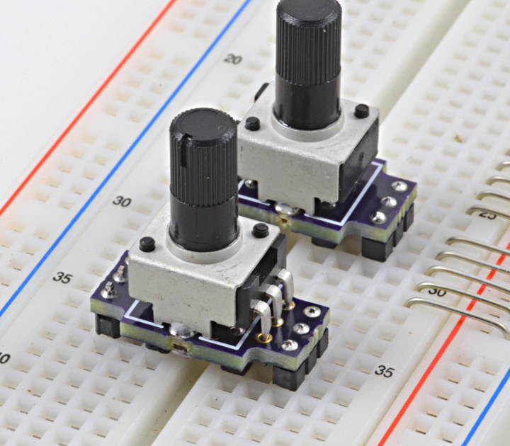
Often I make a quick demo involving pots to adjust parameters. I needed a good way to put pots on solderless breadboards.
I had been doing this way:
These little thumbwheel pots work, but they’re not easy to turn, and trying to turn them puts quite a bit of stress on the loose breadboard connections. They’re also too low to the surface, so people’s fingers get close to the wires and risk disconnecting them.
Socially, I’ve observed people tend to feel awkward touching these… maybe they don’t want to break my project? Or maybe it’s just not clear if they’re supposed to be touched and adjusted?
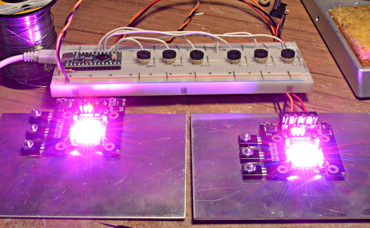
With knobs on top of the pots, a last-minute project really looks like something you’re supposed to touch!
The ones in this video are actually the first version I made, with only 6 header pins. Those worked, but they still weren’t as strong as I wanted.
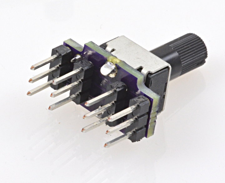
My latest version adds another pair of pins. It’s *really* strong and secure when plugged into a breadboard.
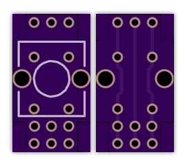
The PCB is so very simple.
They can be ordered from OSH Park, if you’d like to have some for your next breadboard-based demo.
The pot used on these photos is Digikey # PTV09A-4020U-B103-ND. This is a very standard pinout for 6mm shaft pots, so many others are likely to work fine.
The colored knobs were ordered from a no-name Chinese merchant on Ebay. Searching on Ebay for “knob 6mm shaft” will bring up *lots* of them. These gray ones with colored tops were 10 piece for $1, with free shipping. The ones I got didn’t actually fit the 6mm shaft until I ran a drill bit into the center, but it’s hard to complain when they’re so incredibly cheap.
Best of all, real knobs with bright colors and sturdy construction really invite people to touch and adjust and play with a breadboard constructed demo, in fun ways that just aren’t socially feasible with trim pots!
This article was originally published on the DorkbotPDX website, on August 14, 2015. In late 2018, DorkbotPDX removed its blog section. An archive of the original article is still available on the Internet Archive. I am republishing this article here, so anyone wanting to make these sturdy pot boards can find the original info.
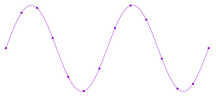
Normally sine waves are generated on microcontrollers using a table lookup.
Lookup tables are perfect when wavelength happens to be an exact multiple of the sample rate, because you never actually need to know the values in between the table’s stored points.
But if you want to generate waveforms at any frequency without changing your sample rate, you end up needing points on the waveform that are between two entries in the table. Four approaches are possible.
Use the prior point, even if the next point would have been better
Use the prior or next point, whichever is closer
Use both nearest points with linear interpolation
Use 3 or more nearest points, with spline or other non-linear interpolation
With any of these, larger lookup tables give better accuracy. Since sine waves have symmetry, some programmers choose to store only 1/4 of the waveform and add slight overhead to map the other 3 quadrants onto the smaller table.
The Teensy Audio Library uses approach #3 for normal sine wave synthesis. The vast majority of sine wave examples in the Arduino ecosystem use approach #1.
If you want a sine wave with extremely low distortion, where 16 or 20 or even 24 bits are within +/- 1 from an ideal sine wave, you would need an extremely large table!
Ideally, you’d want to be able to very rapidly compute an accurate sine value for any 32 bit resolution phase angle, so your samples always line up to an ideal sine wave.
Sine can be computed using Taylor series approximation. The formula is: (where x is the angle, in radians)
This series goes on forever, but each extra terms makes the approximation rapidly converge to the true value. In doing quite a lot of testing, I discovered the C library function on Linux for sin() uses this approximation, to only the (x^7)/7! term. I also found a few sites talking about going to the (x^9)/9! for “professional quality” audio.
One nice advantage of cutting off the Taylor series with on of the subtracted powers (3, 7, 11, etc) is the tiny remaining error will always be slightly less than the true ideal sine value. This means the final result does not need be checked for greater than 1.00000 and rounded down to fit into the maximum value of an integer.
If you’re still reading by this point, you’re probably shaking your head, thinking this couldn’t possibly be practical in a microcontroller. That’s a complex equation with floating point numbers, and huge values in x^11 and 11!, since 11 factorial happens to be 39916800.
However, this Taylor series equation can be computed very efficiently, by exploiting the Cortex-M4 DSP extension instructions and bit shift operations, where the phase angle from 0 up to 2π is mapped from 0x00000000 to 0xFFFFFFFF.
The code I’m sharing here implements this equation to the (x^11)/11! term using 32 bit integers, using only 12 multiply instructions, which execute in a single cycle on Cortex-M4. The add & subtract take zero CPU time, since those multiply instructions also come in flavors that do a multiply-and-accumulate, either positive or negative accumulate.
The Cortex-M4 multiplies perform a 32×32 to 64 bit multiply, and then discard the low 32 bits, with proper round off. That turns out to be exactly the right thing for managing the huge values of x raised to an increasing power, and the huge numbers of the factorials. Since those divisions are by constants, it’s possible to multiply by the reciprocal to get the same effect.
// High accuracy 11th order Taylor Series Approximation
// input is 0 to 0xFFFFFFFF, representing 0 to 360 degree phase
// output is 32 bit signed integer, top 25 bits should be very good
static int32_t taylor(uint32_t ph)
{
        int32_t angle, sum, p1, p2, p3, p5, p7, p9, p11;

        if (ph >= 0xC0000000 || ph < 0x40000000) {
                angle = (int32_t)ph; // valid from -90 to +90 degrees
        } else {
                angle = (int32_t)(0x80000000u - ph);
        }
        p1 =  multiply_32x32_rshift32_rounded(angle << 1, 1686629713);
        p2 =  multiply_32x32_rshift32_rounded(p1, p1) << 3;
        p3 =  multiply_32x32_rshift32_rounded(p2, p1) << 3;
        sum = multiply_subtract_32x32_rshift32_rounded(p1 << 1, p3, 1431655765);
        p5 =  multiply_32x32_rshift32_rounded(p3, p2) << 1;
        sum = multiply_accumulate_32x32_rshift32_rounded(sum, p5, 286331153);
        p7 =  multiply_32x32_rshift32_rounded(p5, p2);
        sum = multiply_subtract_32x32_rshift32_rounded(sum, p7, 54539267);
        p9 =  multiply_32x32_rshift32_rounded(p7, p2);
        sum = multiply_accumulate_32x32_rshift32_rounded(sum, p9, 6059919);
        p11 = multiply_32x32_rshift32_rounded(p9, p2);
        sum = multiply_subtract_32x32_rshift32_rounded(sum, p11, 440721);
        return sum <<= 1;
}
On top of the 12 cycles for multiplies, there’s a few bit shifts, and a quick conditional test which subtracts from a constant. That’s necessary because the Taylor series approximation applies only if the angle is between -pi/2 to +pi/2. For the other half of the sine wave, that subtract maps back into the valid range, because the sine wave has symmetry.
This function takes a 32 bit angle, where 0 represents 0 degrees, and 0xFFFFFFFF is just before 360 degrees. So the input is perfect for a DDS phase accumulator. The output is a 32 bit signed integer, where 0x7FFFFFFF represents an amplitude of +1.0, and 0x80000001 represents -1.0.
This code will never return 0x80000000, so you don’t need to worry about that case.
I did quite a lot of testing while working out these constants and the bit shifts for correct numerical ranges. I believe the top 25 bits are “perfect”. Six of the low 7 bits are very close, but the approximation does diverge slightly as the angle approaches pi/2 magnitude. The LSB is always zero, since the computation needs to have extra overhead range to accommodate values representing up to ~1.57 (pi/2) before the latter terms converge to the final accurate value.
For 8 bit AVR, this approach probably isn’t practical. It probably isn’t practical on Cortex-M0+ either, since there’s no 32×32 multiply with 64 bit result. Cortex-M3 does have such a multiply, but not in the convenient version that rounds off and discards the low 32 bits. On Cortex-M4, this code runs very fast. In fact, when executing at 100 MHz or faster, it might even rival the table lookup, since non-sequential flash accesses (for the table) usually involve a few wait states for a cache miss. Then again, this code does have 6 integer constants, for the conversion to radians and the factorial coefficients… and depending on compiler flags and flash caching behavior, loading those 6 constants might be the slowest part of this algorithm?
I’m sure most people will still use table lookups. Linear interpolation between the nearest 2 table entries is fast and gives a result good enough for most applications. Often a large table is also works well enough, without interpolation. But I wanted to take a moment to share this anyway, even if it is massively overkill for most applications. Hope you find it interesting.
UPDATE: Josy Boelen mentioned alternate forms for Taylor series approximation which require fewer multiplies. Whether these could also be optimized with the M4 DSP extension instructions (not keeping full 64 bit resolution at every step) could be a really interesting future project…
This article was originally published in January 2016 (archive.org link) on the DorkbotPDX site. Since then, the DorkbotPDX blog section has vanished. I’m reposting it here with slight edits and a couple waveform plots, to preserve the info, and also because Michael Field recently asked for an article about these sorts of numerical approximations (which are rarely given as highly optimized fixed-point source code).
This article was originally published in 2011 (archive.org link) on the DorkbotPDX site. Since then, the DorkbotPDX blog section has vanished. I’m reposting it here, to preserve the info. Even though LED strips are far more popular today than el wire, maybe this old info and code might still be useful? What follows is the original text from June 2011, with as many links updated as possible.
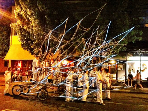
The lighting wasn’t very bright, but there were 114 computer controlled circuits. It was really the only float in the whole parade where the lights “did something” (Robin’s description). Indeed they blinked and faded in lots of complex patterns.
Laurence talked with Steve who’s a Dorkbot regular, who put her in touch with Mykle. Of course, Mykle’s interested in all types of lighting, and he posted it to the mail list on April 22. We all met up for the first time on May 9th and agreed on a rough plan involving a number of the Sparkfun el wire controller boards. All the el wire and controllers arrived on Friday May 13, the day Hand-Eye held a big party to celebrate the launching of the project, or something like that.
I did the electronics and software design part from the 14th to the 19th, and dropped off 2 working controllers and picked up lots of parts that were ordered on the 16th and had just arrived.
Originally Mykle and I had planned to use a perl script (which Mykle would write) to convert an XML export of Laurence’s Adobe After Effects animation (eg, the one you see in that video on Vimeo).
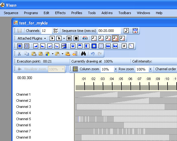
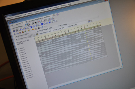
Vixen comes with plugins to communicate with a number of controllers people have created, and one of them looked particularly promising…. the Renard protocol. Several controllers have been made with PIC chips to control ordinary incandescent lighting. None were available for el wire, but the protocol allowed plenty of channels and didn’t require super fast baud rates, and supported 255 brightness levels. So I decided to just program the Sparkfun controllers to accept Renard input.
The Sparkfun el wire controllers were very problematic, but they were pretty much the only off-the-shelf board available. If I had to do this all over again, I would NOT recommend them. I’d make my own.
Here is the firmware I wrote for the Sparkfun boards. It allows each board to be any 8 channels, between 1-8 to 113-120, by placing jumpers on the header on the left side of the board. The boards don’t come with this header… I added to to each of them. Here’s how the jumpers configured each board.
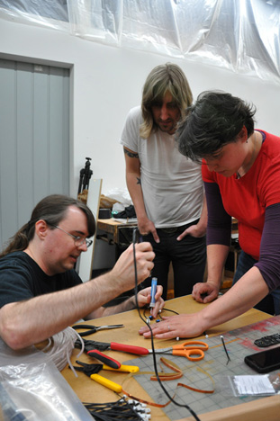
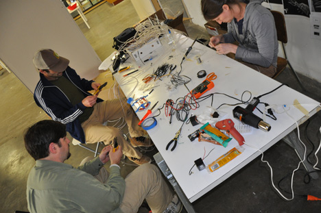
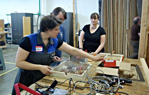
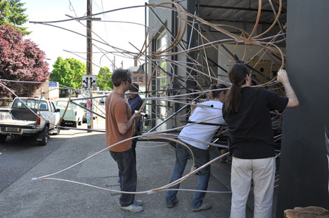
So, with 2 boards talking Renard protocol, on May 20th Laurence began a series of soldering parties. Here’s photos from the first soldering session, held at Hand-Eye Supply’s workshop.
(yup, that’s me soldering in this next photo… though I can’t recall what it was for, maybe a posed shot?)
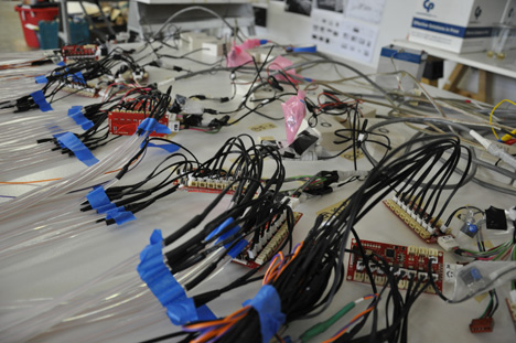
Here’s a photo with a test (done a few days later) with just those first 2 boards. For about a week, only these first 2 boards were working while I modified all the others.
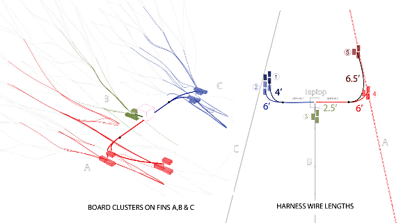
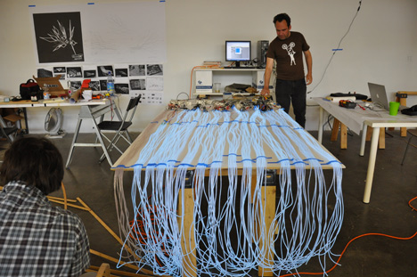
Mykle began work on a cable harness that would distribute data from a laptop running Vixen to all the el wire controller boards… 15 of them. Here’s a diagram of the harness design.
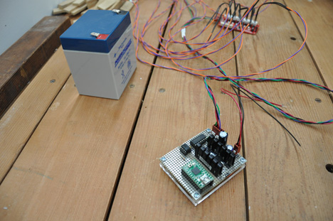
As you can see, the controllers are located in clusters. I mage a transmitter boards, using a Teensy 2.0 running the USB to Serial sketch, on a little hand-wired board with an opto coupler (who wants to hook a nice Mac laptop to a system of 15 high voltage el wire inverters?) and a 5 volt power supply, and buffer with poor-mans slew rate limiting (resistor-capacitor filter) to drive the long cable.
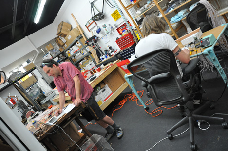
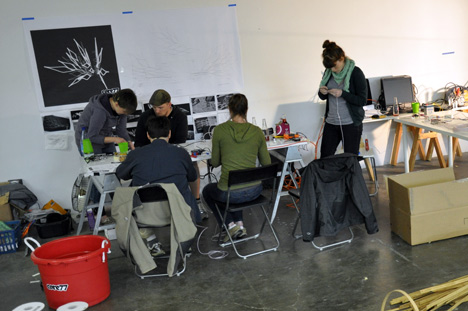
Somewhere shortly after the 20th, construction moved to ADX – which is a great space for building up a big project like this.
Here’s a photo of one of the early soldering parties at ADX.
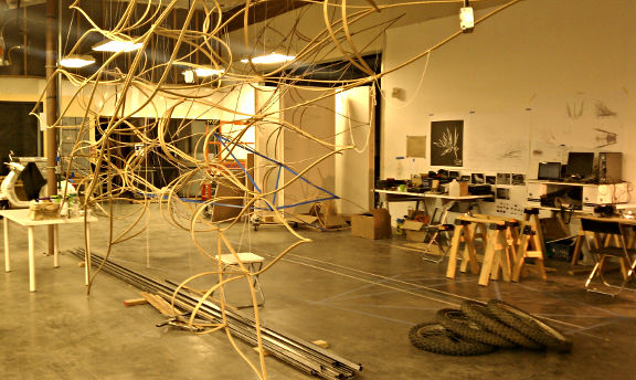
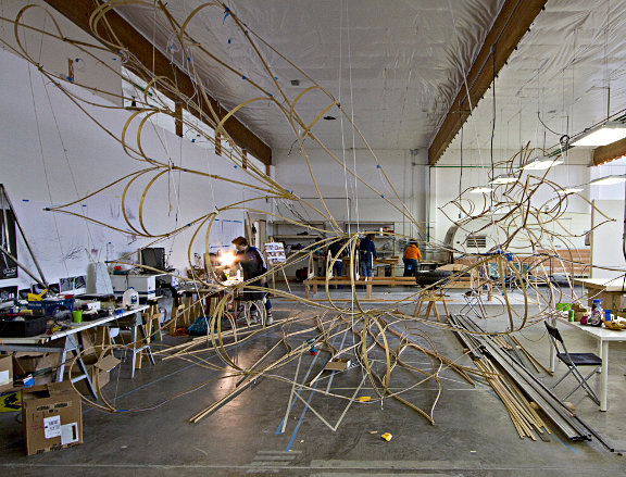
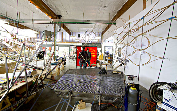
Here’s a photo from May 29th, as the bamboo pieces were starting to be assembled, and the steel which would be welded into the entire frame of the float had just arrived…
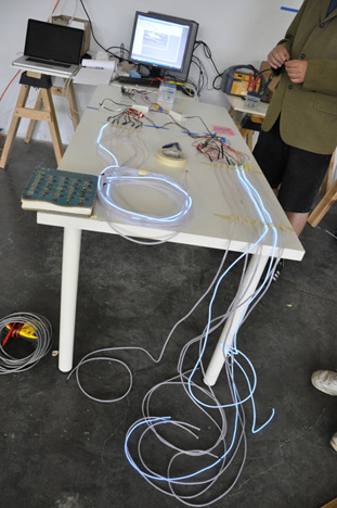
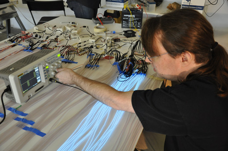
The electronics were all delivered on May 23rd for a full system test. There was a last minute problem with the cable, so only 2 boards were able to receive communication on the 23rd. Here’s that test, where I’m checking to see if the Sparkfun boards are having more troubles.
Mykle made some changes to the cable, and on May 24 the entire electronics package was verified to be working. I believe this was the only time, except for only an hour before the parade, where all the el wire was actually hooked up!
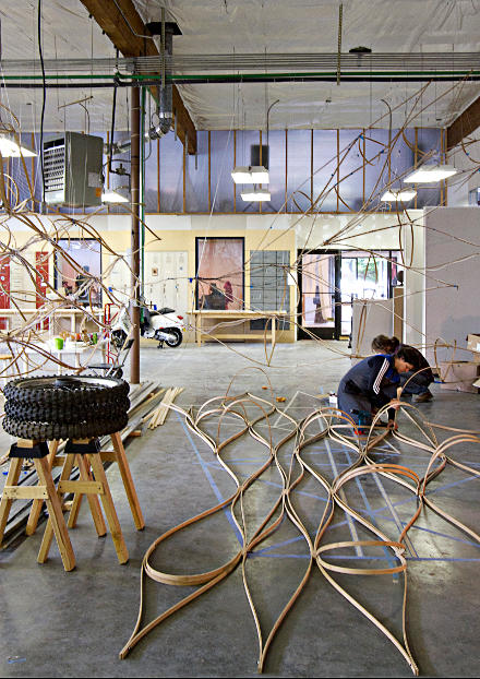
Building a float is a lot of work!!! I wasn’t really involved in the construction much, until the weekend of the parade. Laurence had quite a crew of dedicated volunteers, many of them students from the art institute. They put in a lot of work building the whole thing.
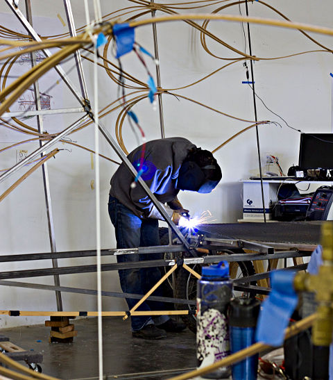
Not only did they build a huge number of these flowing structures from bamboo, but the entire frame of the float was welded together from raw steel. Pretty amazing. I wasn’t involved in any of this part. These photos were taken by ADX.
I stopped by on Thursday, June 2nd (2 days before the parade), and June 3rd (the night before, while ADX was having a huge grand opening party). Robin & I met there, I dropped off some parts and we had dinner out. Robin being so understanding about projects like this was ok with me staying there after our dinner out and working on it pretty late.
Here we are right before going out to dinner, and Robin’s really hungry and waiting while we try to figure out how the electronics will attach!
I went by Saturday (the date of the parade) and helped from about noon until the parade. Most of the lights were on the float, but none wired to the controllers, which had just been mounted that morning! I spent much of the time getting Mykle’s cable connected, and one of the groups of controllers had to be remounted for the cable to reach. It’s amazing how many little things all need to be solved.
As things wrapped up at ADX late in the afternoon, we lit up the lights for the first time actually on the float, and it was indeed an awesome moment seeing it was indeed going to work, even if less than half had been wired in by that point.
Getting the float from ADX to the parade staging are was another adventure… one for some else to write…….. Here’s a photo of the last part I saw at ADX, as it was being wheeled out onto the street to be (somehow) attached to a truck.
I actually left as they were hooking it to a truck to go meet up with Robin in NW for dinner near the parade. The brought it across the river to the parade staging area while Robin and I had dinner.
We both helped, and in those last few hours and amazing number of wires were all attached…. Beer was consumed too. 🙂
Tobias had created a number of sequences in Vixen. Sadly, there hadn’t been any time to test them with the wires attached, and efforts to map out which wires were on which channels just weren’t feasible in the daylight. El wire just isn’t really bright. Still, it was pretty impressive, if much more randomly flashing than the animations Laurence had originally envisioned.
With everything in place, Robin and I left and walked a few blocks to the beginning of the parade and set up a couple camping chair Robin had packed. We had a pretty good view.
Just as the parade was starting and the first couple (of many) marching bands went by, my phone rang. The computer had crashed and the float wasn’t working. I ran back. It was a mac and Windows was running in a virtual machine, so at least the host OS was fine. Somehow Windows had crashed. Some fiddling, plugging in to the different ports and installing drivers fixed the problem.
I returned to Robin and as the parade went by, I was a little worried it wasn’t dark enough for the el wire. Luckily, Hand-Eye Supply was #82 in the parade, so they entered around 9:30 and it was quite a bit darker by them. It still wasn’t nearly as bright, but the lights did flash and fade in lots of patterns.
With so much coming together so quickly in just a few weeks, with all those wires connected within hours of the parade, I was pretty amazed it worked. Then today, Mykle emailed the KGW story that Hand-Eye Supply’s float won the 1st place award!! 🙂
This little project was inspired by Mykle’s Lightbar message on December 2. Well, probably intending to help prior years was a factor. Anyway, here’s that message:
Subject: [dorkbotpdx-blabber] LIGHTBAR cometh … LED help?
hi dorky people!
to any of you who remember LIGHTBAR from two years ago, or heard about it, i’d like to announce that LIGHTBAR 2011 is in the planning stages for this February.
LIGHTBAR is a Seasonal Affective Disorder (SAD) treatment center that appears intermittently in the month of February to bring inspiration, fresh air and wide spectrum light to the people of Portland.
This year I’m working on a Mobile LIGHTBAR system — a folding portable structure. But there’s some tricky parts I’m trying to overcome regarding the light itself.
For one: we’re going to be generator powered at best, so I’m investigating low-power lighting options. LEDs were not really wide-spectrum last time i checked, but maybe they’ve gotten better? Can anybody suggest types of LED lighting wider than the standard white and RGB varieties we’ve had bouncing around since 2005? I’m just not up on the latest LED fashions, I guess.
For two: I’m looking to rent or borrow a portable gas generator during the month of February. I’m asking everybody, yourselves included. I will treat it like a baby.
For three: My Mobile LIGHTBAR will have a folding skin, and I’d really like to integrate some kind of LED lighting system directly in the fabric, or else on some kind of net that easily hangs between the skin and the frame. this would be your standard controlling-a-bunch-of-LEDs project, but it has to be designed for durability, ease of repair, and fairly long runs of cable. If it was all RGB LEDs and they were independently addressable, that would be even better. Probably I’d be talking about something in the range of 100 – 200 LEDs, of 1 watt or less. (roughly!) Picture trying to spread those evenly across a 20′ diameter hemisphere, with the power & control system located somewhere on the edge.
I’ve thought about doing this with the BlinkM units, since they’re bus-addressable, but I feel like with this many units it might be cheaper to have something custom-fabbed. on the other hand, time is tight. i’d be thrilled if i could find system already designed to do exactly this.
and/or, does anybody in Dorkbot feel like taking this on as their own project? i think i could find some budget …
-m-
So, I started looking at some RGB LED specs. I pretty quickly found that the lower power LEDs, like the one on BlinkM, aren’t specified in Lumens (total light output), or if they are, the Lumens per Watt aren’t great.
After comparing lots of LEDs, I finally ended up with ASMT-MT00, which is in the 30-some Lumen/Watt range. It’s not cheap (about $10 to $15 in small qty), but it really works!
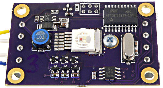
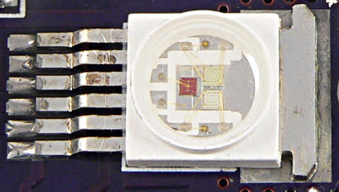
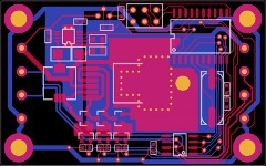
Here’s a close-up of the LED.
Today many more high power LEDs are available, some from Chinese sellers with questionable specs, but so cheap they’re hard to pass up! Back in 2011, this seemed like the best option.
Mykle wanted to keep the cost low. In fact, he wanted to use cheaper LEDs… But this was my little weekend project-on-a-whim, and I wanted 100+ lumens! I also really wanted to make it run on 12 volts and have very efficient conversion and tolerate some voltage drop without changing the LED brightness, and I wanted RS485 communication so the signals can run a long distance (unlike BlinkM). This design does all that. In the end, it worked really well for Lightbar… so well that Mykle is building 18 more boards!
Pretty much on a whim, I ordered a few ASMT-MT00’s and other parts, and came up with a somewhat unconventional design.
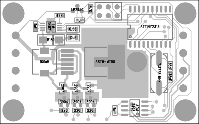
IC manufacturers generally recommend using 3 of their LED drivers for RGB LEDs, one for each color. Of course, they love to sell 3 specialized chips, which aren’t cheap! Instead, I decided to try using only 1 special power supply chip, and the LM3407 from National Semiconductor looked like one of the most economical (cheapest) choices. And I was going to use only 1 instead of 3.
The basic idea was run all 3 LEDs in series. The ASMT-MT00 nicely provides each LED separately on 6 pins, instead of common anode or common cathode, which makes this possible.
The LM3407 can operate without any output capacitor. It is a constant current afterall. Normally a 22 uH inductor would be recommended. But I decided to increase it to 100 uH (the datasheet is light on details of stability in continuous vs discontinuous mode, but it seemed like continuous conduction buck mode would work). The LM3407 datasheet mentions being able to omit the output cap, with increased variance in output. Since I wasn’t going to have any output cap, I wanted the current to be better regulated, and upsizing the inductance is the way to do it.
The reason to omit the output capacitor is because I decided to change the color by diverting the current around each LED. Red is about 2 volts, and blue and green about about 3.5 volts. But when shorted by a PNP transistor, the voltage suddenly changes to about 0.5 volts. Better transistors would be less than 0.5, but I used cheap 2907’s.
Since the PNP transistors basically “float” at whatever voltage the power supply and drop on other LEDs or transistors happen to make, I used 3904 NPNs so a microcontroller can turn on and off their base current. When the processor drives 3.3 volts, about 2.6 volts is driven onto the 220 ohm resistor on the emitter, or about 12 mA in the 220 ohm resistor. That 12 mA comes mostly through the collector (which doesn’t care what it’s voltage happens to be when used in linear mode), which pulls the current from the floating PNP transistor base.
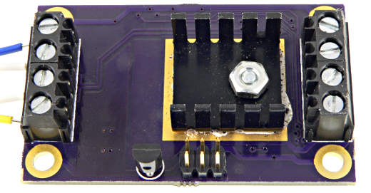
Yes, this is a pretty unusual transistor circuit… and I wasn’t completely sure if it’d work, but this whole thing was just a whim. I spend 2 days on it, the first one reading about the LEDs, LM3407 (and lots of other chips), and thinking about that circuit. The second day, I drew up the circuit board. I knew the LED gets hot, and so would the LM3407 and maybe the transistors too? I just drew some copper planes and thermal vias, and a big pad for a small heatsink (leftover from another old project). No prototype, no simulation, no real analysis… just a lot of guesswork and hunches, and at the end of the second day I sent off the files to Laen’s PCB Order (which is now OSH Park).
I never drew any schematic for the rest, but it’s just a ATTINY2313 chip to control everything. There’s 4 PWM signals, 3 connected to the transistors, and the 4th to the “DIM” control pin on the LM3407, so it can shut off when none of the LEDs need to be on. There’s also a RS485 interface chip and a few other necessary parts, but nothing really special.
If anyone actually builds more boards (Mykle is building 18 more), here’s a parts placement diagram:
I pretty much set this thing aside and forgot about it, until the boards arrived a few weeks later. I set them aside for a few days, but the Dorkbot Monday meetup was the motivation I needed to get them actually working!
Then I spent one late night session Sunday night building and testing the hardware. Amazingly, the LM3407 chip worked great. I was worried the current regulation might respond too slowly when the output voltage suddenly changes by 3 or 6 or 8 volts! But it works great (at least without any output capacitor). It is designed by be PWM controlled by the DIM pin… but there weren’t any specs about how it’d respond to the ‘LED voltage” suddenly changing. I actually spent a couple hours with an oscilloscope and waveforms driving onto the transistors to make sure it really worked.
The other thing I tested and verified, is the switching power supply really does efficiently convert the power and adjust as the color changes. Even though the current is still “on”, when 2 of the lights are off, the voltage is only 0.5 volts (the cheap 2907 can’t get it any lower). Because power is voltage * current, the input current really does go down even though the output current stays the same, because the output voltage changed, and the switcher is pretty efficient. It really does work well that way. The switcher also does a great job of making exactly the same output, even if the input drops to 10 volts instead of 12.
About mid-morning Monday, with the Dorkbot meetup looming only hours away, but the hardware pretty well tested, I started working on the software side.
One confession I need to make is the ISP header was routed for the usual pinout with the header on the “top” side, but I soldered it to the “bottom” side (the side with the heatsink). Fortunately, I had a Teensy with ArduinoISP sitting on my desk, so it was pretty easy to just reverse the pinout to match. But if anyone else builds this little board and tries to use an off-the-shelf AVR ISP programmer, well, either solder the header to the LED side, or plan on wiring up a little adaptor to reverse the pinout.
In about an hour, I banged out this extremely simple code to run on the ATTINY2313 chip.
It listens for 8 character ASCII commands at 115200 baud. The input is hex, where the first byte is the board’s address, and the next 3 bytes are the RGB color. Any non-hex byte causes it to discard any data and begin listening for a new comment. Normally, sending a byte like “:” before a command, or pressing Enter after each command is a good idea. Here’s a few commands:
01FFFFFF Board #1, White
030000FF Board #3, Blue
02000000 Board #2, Off
Each board needs to have its address hard-coded. The makefile runs AVRDUDE automatically, so this isn’t very difficult.
Mykle has already added some new features to the code, like a broadcast address. I don’t have his latest code, but he’s planning to set up a CVS (or similar) server for the code. Hopefully he’ll post a reply below with a link.
The code could do a lot of things. The address bytes could be stored in EEPROM, instead of hard-coded. The protocol could be extended, or features like BlinkM could be added. Even DMX should, in theory, be possible.
I spent about 1 hour on the code. Much of that was making the PWM polarities correct.
With a few extra hours to spare before Dorkbot that Monday evening, I did some fiddling to make the lights work with Puredata. All 3 boards I made were working well that night.
I must confess, I’m not very experienced with Puredata. But quite a Dorkbot regulars are. Jason, Brian and others hacked on the Pd stuff and made the LEDs blink and fade. Here’s the Puredata Code, both my original attempts, and the end result of hacking on the code during 1 evening at Backspace.
The evening, Mykle took home the 3 boards, and a RS-485 converter I had (left over from other projects). They were used at Lightbar, and I made it out there one of the evenings. Good times.
Mykle is building 18 more lights, and plans to do fun things with the software.
I’m not planning to do much more with this, but I wanted to get this blog post written, so the info, and all the available design files and code would be posted publically. If you, dear reader, build these or use the ideas or info for another project, please post a comment below.
Enjoy!
This article was originally published on the DorkbotPDX website, on March 22, 2013. In late 2018, DorkbotPDX removed its blog section. An archive of the original article is still available on the Internet Archive. I am republishing this article here, in the hope it may continue to be found. But today, many awesome addressable LED products exist on the market, so this sort of project probably doesn’t make good economic sense compared to just buying a ready-made LED strip.
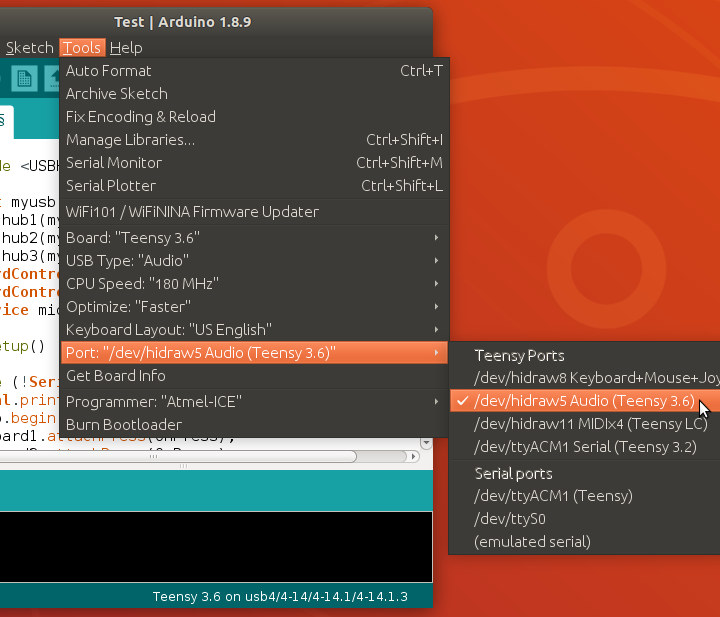
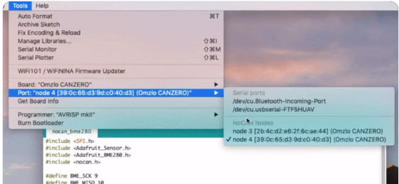
In this article, I’ll dive into the details needed to use Pluggable Discovery. But first…
A Brief History
Since the first Arduino software in 2005, the main way to upload code to boards has been by serial ports. In 2008, support for in-circuit programmer hardware was added, where you select a type of programmer rather than a port. In 2013, port detection and selection in the Ports menu was expanded to include network ports for Arduino Yun. Around that time, Arduino also became highly configurable by recipes in platform.txt, based on a major contribution from Mark Sproul & Rick Anderson. But until now, Arduino has supported detecting only 2 types of ports, either serial or network (using Yun’s specific protocol), with the only way to customize being dedicated programmer hardware. Protocols other than serial & Yun’s network just weren’t supported for the Ports menu.
Teensy has used HID protocol, not Serial, for code uploading since its launch in 2008. Using Teensy with Arduino was somewhat awkward. When running a program implementing USB Serial, Teensy would appear in Arduino’s list of serial ports. But with HID or other non-serial protocols, no port would be shown. Teensyduino’s upload process could automatically detect Teensy in those modes, so uploading would “just work” even though the ports menu indicated no ports available. When things went wrong, like this infamous Windows 7 driver bug, lack of reliable ports display made confusing situations hard to understand.
In early 2017, I started work to improve how Teensyduino integrates with Arduino. A dedicated “teensy_ports” utility watches for Teensy’s USB devices to be added & removed. Inside the Arduino IDE, I added a 3rd type of port to the DiscoveryManager class, using this utility’s info. Finally, Teensy could be seen in the Ports menu even with running in a non-Serial mode. You could choose exactly which board to use for upload, rather than hoping the automatic detection would find the right one.
In a June 2018 conversation with Massimo Banzi, Cristian Maglie and other Arduino developers, it was decided that I would contribute this code to Arduino. A flexible JSON format would replace the original single-line text, so anyone could use it, and Arduino can adapt the format in the future. After a lengthy process, where Cristian rewrote and greatly improved the JSON parsing, in March 2019 Arduino 1.8.9 was finally released with this new “Pluggable Discovery” feature.
JSON Data Format
The first step to using Pluggable Discovery is to write a “discoverer” utility which sends information to the Arduino IDE as your board is connected and disconnected. Data is sent to Arduino on stdout, and Arduino may send you commands on stdin.
Here is a sample of the JSON data “teensy_ports” sends to Arduino 1.8.9 when running on Linux.
Here is a quick attempt to document these fields. Please understand these fields may change meaning, or others may be added by future Arduino releases. Hopefully in the future Arduino will add official documentation for this JSON format.
eventType: Either “add” when a device is detected and Arduino should begin showing it in the Ports menu, or “remove” when disconnected and the Ports menu should no longer show it. If information changes, or more information becomes available, multiple “add” messages may be sent to cause Arduino to update the Ports menu. The eventType “error” is also supported. See Discoverer Commands below for details.
port: A container for all of the information about the port.
address: A unique identifier for this port. The address is not shows in the Ports menu, but does appear in the status bar on the bottom of the Arduino IDE windows when the port has been selected. The address is the primary info you would give to your uploader utility. See “Integrating With Your Uploader” below for details.
protocol: A unique (or at least distinctive) name for the communication protocol the port uses. Currently Arduino 1.8.9 ignores this field, unless it is “serial” or “network”. This name can be passed to your uploader utility.
protocolLabel: The name of your type of port, as shown in the title of a sub-section of the Ports menu. Currently there is no way to adapt this field to different languages. This info can also be passed to your uploader utility, though typically the “protocol” field would be used rather than this name meant for display to the user.
boardName: The name of the board. This should probably match one of the names you define in boards.txt, though Arduino 1.8.9 does not currently enforce any requirements.
label: The human readable name for the port, to be shown as a selectable item in the Ports menu.
identificationPrefs: Arduino 1.8.9 does not make any use of this field.
prefs: This is meant to collect info about the port, such as the info shown by “Get Board Info”. However, Arduino 1.8.9 does not make use of this field for non-serial ports. Hopefully future versions will fix this.
online: While not used by Arduino 1.8.9 for non-serial ports, this should normally be “true” when eventType is “add” and “false” when eventType is “remove”. With serial ports, the port’s online status can be momentarily false when Arduino is attempting to send a command to the board to automatically reboot into its uploading or bootloader mode.
When a port should be deleted, only the eventType and address fields are required. Here is a sample of the JSON remove message teensy_ports transmits.
Like all programs which print to stdout, buffering may exist between your output and Arduino’s reception. Composing the entire JSON message in a buffer, then using a single write and flush to stdout is the most efficient way. Arduino is using the Jackson library to parse your JSON messages, so sending piecemeal, with or without newlines or other optional white space should also work.
Discoverer Commands
The Arduino IDE will also send your discoverer commands on its stdin stream. These are not JSON. They are plain text commands, terminated by a single newline character.
START_SYNC – Begin running in sync mode, where your program transmits JSON messages automatically as the device change events occur.
START – Begin running in polled mode, where Arduino will send a “LIST” command at regular intervals.
LIST – In polled mode, this command is meant to prompt your program to scan for changes.
STOP – Stop running.
Future versions of Arduino may behave differently, so please understand the following behavior is specific to version 1.8.9.
When Arduino runs your discoverer, it will send a single START_SYNC command. If you do not need polled mode, no response is needed or expected. Your program simply transmits JSON messages as it detects ports, starting with “add” eventType messages all the ports currently available, and then more “add” or “remove” messages as available ports change.
If you require polling mode, you would transmit this JSON message.
{
  "eventType": "error",
  "message": "START_SYNC not supported"
}
Upon receiving this message, Arduino should transmit “START” and then send “LIST” at regular intervals. If your discoverer is unable to detect hardware changes as they occur, you can design your code to wait for “LIST” and then check whether ports have changed.
With polling, typically you would need to design your discoverer to keep in memory a list of the ports it has previously transmitted to Arduino. When you poll which ports are actually available, your discoverer is responsible for detecting when any port you have previously transmitted an “add” eventType is no longer present. You must transmit the “remove” eventType, to cause the Arduino IDE to no longer offer that port to users in the Ports menu.
A list of previously detected ports can also help you avoid repeatedly sending the same info as your discoverer checks which ports currently exist. But this is not required. As long as the “address” field remains the same, Arduino Pluggable Discovery treats a redundant “add” eventType as a request to update the port’s info. Sending the same info repeatedly is inefficient, but harmless.
Polling mode may not be working properly in Arduino 1.8.9. Most testing was done with sync mode.
Arduino 1.8.9 transmits STOP only when the user closes the entire IDE, just before your program is terminated. There is no guarantee your discoverer will continue running long enough to actually receive the STOP message.
Future Arduino software may send START_SYNC, START and STOP at different times, but with 1.8.9 the start messages are used only as the Arduino IDE starts up, and STOP is sent only when the user quits the software.
Running Your Discoverer
Like everything else customizable in modern Arduino, you create a recipe in your platform.txt file which tells Arduino to run you discoverer. Here is a recipe for “teensy_ports”.
This recipe assumes the teensy_ports utility is installed in the hardware folder, inside the Arduino software. Because the recipe starts with “discovery”, Arduino 1.8.9 detects it is a command for a pluggable discovery program. It will be run as Arduino starts up. Use of {runtime.ide.path} only works if your discover is copied to a locating inside Arduino’s folder.
The “-J2” is parameter given to “teensy_ports”, the same as if you had typed “./teensy_ports -J2” on the command line. While unlikely to be needed, you can build almost any command line your discoverer might need. In this case, the JSON format changed during development, so “-J2” tells teensy_ports with JSON dialect to output.
Now that your discover can find your board’s custom port, and the user can select it in the Ports menu, you need a way to actually pass the detected info to your board’s uploader program.
Fortunately this part is easy. The macro {serial.port} in your uploader recipe in platform.txt will be replaced by whatever text your discoverer provided in the JSON “address” field.
Yes, it’s still called “serial.port” in these substitution patterns, even though we can now (theoretically) extend the Arduino IDE any sort of protocol.
While your uploader probably only needs the unique address field and the pathname to find the code Arduino compiled, you can also pass some of the other JSON fields to your uploader. Here is the recipe Teensy is currently using.
Hopefully Arduino will eventually document the mapping from JSON fields to recipe substitution names. These were found by reading the Java source code and some experimentation.
Troubleshooting
What could possibly go wrong?!
Arduino 1.8.9 has a fair amount of debugging code built in to help you see how Arduino is running your discoverer, and what it’s receiving. To enable the debug output, add this line to your preferences.txt file.
discovery.debug=true
If you’re not sure where your preferences.txt file is located, click File > Preferences and look at the info in the button part of the Preferences dialog.
Minor Issues In Arduino 1.8.9
Polling mode may not work.
The substitution macro {runtime.hardware.path} very often used in platform.txt recipes is not yet supported. Teensyduino adds a patch to Arduino 1.8.9 to support this in discovery recipes. If you prefer {runtime.hardware.path}, installing Teensyduino may be a short-term solution. Hopefully this patch will be merged into future Arduino versions.
Other substitution issues may exist in Arduino 1.8.9. Pluggable discovery is brand new.
Pluggable Discovery does not yet exist in Arduino’s Command Line Interface software. Using Pluggable Discovery today means your board’s package can not work with the CLI. Cristian started work on Pluggable Discovery for CLI months ago, but since January there appears to be no progress. Hopefully as more people use Pluggable Discovery to support non-Serial protocols, we’ll see progress on bringing it to CLI as well.
Serial Monitor
Of course the other key Arduino IDE feature missing to truly support boards with any type of port is the serial monitor window. And also the serial plotter.
Teensyduino currently adds several patches to the Arduino IDE to install a customized serial monitor. It communicates, via stdin/stdout/stderr with a “teensy_serialmon” utility program. Hopefully in the future, these patches can eventually be contributed to Arduino as as “Pluggable Serial Monitor” feature which complements Pluggable Discovery.
But at least for now, if you are interested in extending the Arduino IDE to work with boards using completely different communication protocols, hopefully the Pluggable Discovery contribution and this article can help.
Many years I built electronics for Lostmachine Andy‘s fire effects on his awesome pirate ship for Burning Man.
The electronics from this old project were reused in several other propane fire art projects.
To get a better idea of Andy’s amazing Pirate Ship project, check out the video on his kickstarter page. The info about the fire effects starts at 2:58 into the video.
Here is a video where 1 of the 8 fire nozzles was tested in Andy’s driveway!
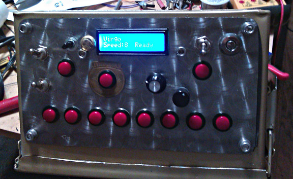
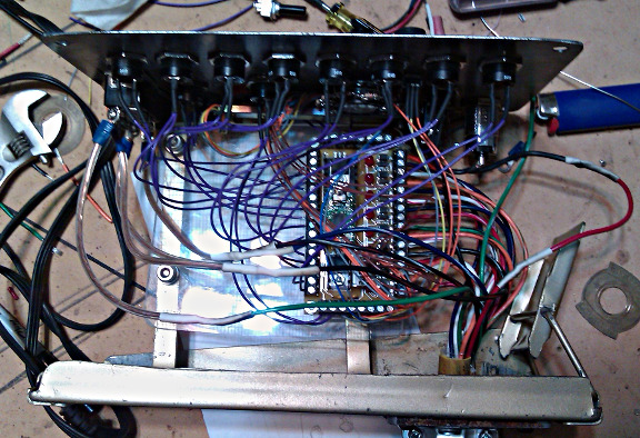
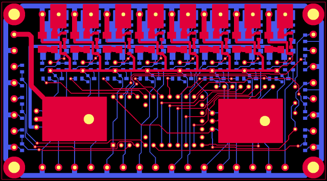
My little piece of this huge project is the circuit board, which you can see in the center of this nice metal box Andy machined.
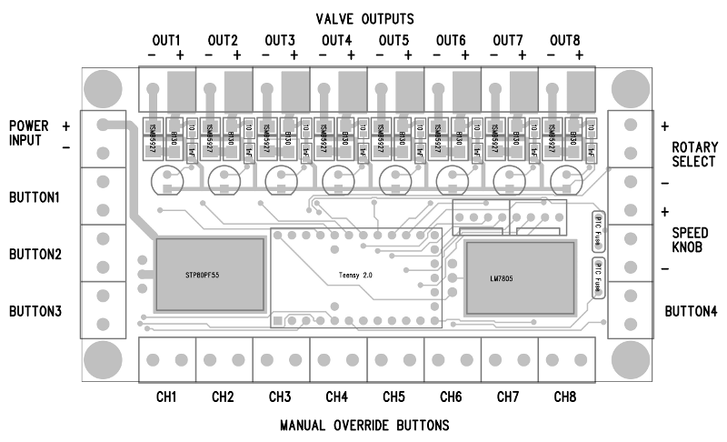
Here are images of the circuit board.
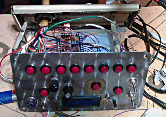
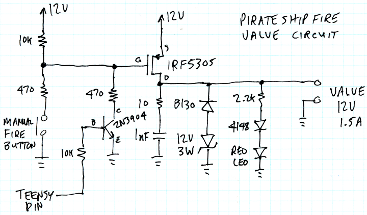
The 8 solenoid valves connect on the top edge. Eight manual fire pushbuttons connect on the bottom edge. Those pushbuttons directly turn on the transistor for each valve. Of course, the software running on a Teensy 2.0 can control the valves too. There’s inputs for 4 buttons and 2 knobs to the software. There’s a place to plug in a 16×2 LCD, which shows info about the sequence to be used.
Circuitry-wise, the board is pretty simple. There’s a big P-channel mosfet at the input, acting as a diode to protect against reverse polarity power. Each valve draws about 1.5 amps, so at 12 amps, a regular diode didn’t seem like a good idea. In the center is a Teensy 2.0 board in sockets, and to the right is a LM7805 regulator. The 5 volt power to the 2 knobs goes through little PTC fuses. The knobs and buttons just wire into analog and digital pins, through some little R-C filters, just in case there’s any radio frequency noise pickup. Since I’m not going to Burning Man this year and can’t be there to troubleshoot, I wanted to play it safe (and it only takes a few extra cheap parts).
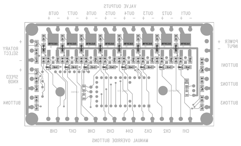
On the top edge are the 8 transistor circuits. There too, I decided to play things safe, perhaps a bit overly cautious? The valves are switched with IRFR5305 P-channel mosfets. Rated at 31 amps, 55 volts, they’re a bit overkill. Then again, I wanted to make sure they wouldn’t get hot, so their on resistance of 0.065 ohms is nice. At 1.5 amps, that ought to be 0.15 watts, which isn’t much at all for a package with a metal tab. A lesser transistor would have worked, but might have needed a heatsink. This PCB was made at Sunstone and just barely fit into 9 square inches. Using heatsinks would have bumped the cost up to the next bracket, which is a lot more than the cost of these nicer transistors.
Andy was concerned about the valves switching quickly. So for the back-EMF catch diode, I used a B130 schottky in series with a 12 volt, 3 watt zener. That lets the valve create -12 volts while discharging, so it ought to switch from on-to-off about as far as off-to-on. We talked a bit about possibly using a very complex approach where the valves might be driven with about 50 volts until they get up to the correct current, and then sustain at the rated 12 volts. Yes, that’s risky, but I’m pretty sure I could do it safely. Maybe after the burn this year we’ll be able to play with the valves and experiment to see if forcing the valve to open and close faster than it can with only 12 volts actually allows any interesting fire effects?
A couple extra overly cautious things I did do were resistors to slow down the gate drive into the microseconds range (still far faster than any mechanical valve can move), and just to be extra cautious, I put a tiny R-C snubber on the output, just in case the transistor somehow switches faster that the reverse recovery time of those diodes. I guess over an amp of current flowing in an almost purely inductive load makes me a bit nervous. Those parts probably aren’t necessary and the 2 diodes are probably all the protection necessary from inductive spikes… but I wanted to play it extra safe since things are so hard to fix out on the playa at Burning Man (especially at night, when the fire will be in use).
So with all this circuitry hooked up, the good news is it’s all programmable with Arduino. Here’s the sketch I delivered to Andy. It reads a 12 position rotary knob and a speed pot, and plays 1 of the 12 sequences when a “Go” button is pressed. There’s a “stop” and “fire all” button, and the 4th button is unused.
While this code is fairly long, and a bit complex in the custom delay and other stuff near the end, I tried to keep the definition of the 12 sequences very simple. Just digitalWrite and the custom delay function.
#include <LiquidCrystal.h>
#include <Bounce.h>

// input pins
const int go_button_pin      = 4;
const int stop_button_pin    = 1;
const int all_button_pin     = 2;
const int speed_knob_pin     = 20;  // analog
const int rotary_select_pin  = 21; // analog

// output pins
const int valve1_pin         = 19;
const int valve2_pin         = 18;
const int valve3_pin         = 17;
const int valve4_pin         = 16;
const int valve5_pin         = 15;
const int valve6_pin         = 14;
const int valve7_pin         = 13;
const int valve8_pin         = 12;
const int lcd_rs_pin         = 5;
const int lcd_en_pin         = 6;
const int lcd_d4_pin         = 7;
const int lcd_d5_pin         = 8;
const int lcd_d6_pin         = 9;
const int lcd_d7_pin         = 10;
const int led_pin            = 11;

const byte valvelist[8] = {valve1_pin, valve2_pin, valve3_pin, valve4_pin,
                           valve5_pin, valve6_pin, valve7_pin, valve8_pin};

// unused pins
const int unused_button_pin  = 3;
const int unused1_pin        = 0;
const int unused2_pin        = 22;
const int unused3_pin        = 23;
const int unused4_pin        = 24;

// Objects for the buttons and display
Bounce go_button(go_button_pin, 10);
Bounce stop_button(stop_button_pin, 10);
Bounce all_button(all_button_pin, 10);
LiquidCrystal lcd(lcd_rs_pin, lcd_en_pin,
  lcd_d4_pin, lcd_d5_pin, lcd_d6_pin, lcd_d7_pin);


#define Pattern_Name_1 "Sweep Left+Right";
void play1()
{
  digitalWrite(valve1_pin, HIGH);
  if (delayCust(150, 100)) return;
  digitalWrite(valve1_pin, LOW);

  digitalWrite(valve2_pin, HIGH);
  if (delayCust(150, 100)) return;
  digitalWrite(valve2_pin, LOW);

  digitalWrite(valve3_pin, HIGH);
  if (delayCust(150, 100)) return;
  digitalWrite(valve3_pin, LOW);

  digitalWrite(valve4_pin, HIGH);
  if (delayCust(150, 100)) return;
  digitalWrite(valve4_pin, LOW);

  digitalWrite(valve5_pin, HIGH);
  if (delayCust(150, 100)) return;
  digitalWrite(valve5_pin, LOW);

  digitalWrite(valve6_pin, HIGH);
  if (delayCust(150, 100)) return;
  digitalWrite(valve6_pin, LOW);

  digitalWrite(valve7_pin, HIGH);
  if (delayCust(150, 100)) return;
  digitalWrite(valve7_pin, LOW);

  digitalWrite(valve8_pin, HIGH);
  if (delayCust(150, 100)) return;
  digitalWrite(valve8_pin, LOW);
}


#define Pattern_Name_2 "Sweep Right-Left"
void play2()
{
  digitalWrite(valve8_pin, HIGH);
  if (delayCust(150, 100)) return;
  digitalWrite(valve8_pin, LOW);

  digitalWrite(valve7_pin, HIGH);
  if (delayCust(150, 100)) return;
  digitalWrite(valve7_pin, LOW);

  digitalWrite(valve6_pin, HIGH);
  if (delayCust(150, 100)) return;
  digitalWrite(valve6_pin, LOW);

  digitalWrite(valve5_pin, HIGH);
  if (delayCust(150, 100)) return;
  digitalWrite(valve5_pin, LOW);

  digitalWrite(valve4_pin, HIGH);
  if (delayCust(150, 100)) return;
  digitalWrite(valve4_pin, LOW);

  digitalWrite(valve3_pin, HIGH);
  if (delayCust(150, 100)) return;
  digitalWrite(valve3_pin, LOW);

  digitalWrite(valve2_pin, HIGH);
  if (delayCust(150, 100)) return;
  digitalWrite(valve2_pin, LOW);

  digitalWrite(valve1_pin, HIGH);
  if (delayCust(150, 100)) return;
  digitalWrite(valve1_pin, LOW);
}

#define Pattern_Name_3 "Alt Side-Side"
void play3()
{
  for (int count=0; count < 6; count++) {
    digitalWrite(valve1_pin, HIGH);
    digitalWrite(valve2_pin, HIGH);
    digitalWrite(valve3_pin, HIGH);
    digitalWrite(valve4_pin, HIGH);
    if (delayCust(90, 75)) return;
    digitalWrite(valve1_pin, LOW);
    digitalWrite(valve2_pin, LOW);
    digitalWrite(valve3_pin, LOW);
    digitalWrite(valve4_pin, LOW);

    digitalWrite(valve5_pin, HIGH);
    digitalWrite(valve6_pin, HIGH);
    digitalWrite(valve7_pin, HIGH);
    digitalWrite(valve8_pin, HIGH);
    if (delayCust(90, 75)) return;
    digitalWrite(valve5_pin, LOW);
    digitalWrite(valve6_pin, LOW);
    digitalWrite(valve7_pin, LOW);
    digitalWrite(valve8_pin, LOW);
  }
}

#define Pattern_Name_4 "Alt Odd-Even"
void play4()
{
  for (int count=0; count < 6; count++) {
    digitalWrite(valve1_pin, HIGH);
    digitalWrite(valve3_pin, HIGH);
    digitalWrite(valve5_pin, HIGH);
    digitalWrite(valve7_pin, HIGH);
    if (delayCust(90, 75)) return;
    digitalWrite(valve1_pin, LOW);
    digitalWrite(valve3_pin, LOW);
    digitalWrite(valve5_pin, LOW);
    digitalWrite(valve7_pin, LOW);

    digitalWrite(valve2_pin, HIGH);
    digitalWrite(valve4_pin, HIGH);
    digitalWrite(valve6_pin, HIGH);
    digitalWrite(valve8_pin, HIGH);
    if (delayCust(90, 75)) return;
    digitalWrite(valve2_pin, LOW);
    digitalWrite(valve4_pin, LOW);
    digitalWrite(valve6_pin, LOW);
    digitalWrite(valve8_pin, LOW);
  }
}

#define Pattern_Name_5 "Mid to Outside";
void play5()
{
  digitalWrite(valve4_pin, HIGH);
  digitalWrite(valve5_pin, HIGH);
  if (delayCust(80, 25)) return;

  digitalWrite(valve3_pin, HIGH);
  digitalWrite(valve6_pin, HIGH);
  if (delayCust(80, 25)) return;

  digitalWrite(valve2_pin, HIGH);
  digitalWrite(valve7_pin, HIGH);
  if (delayCust(80, 25)) return;

  digitalWrite(valve1_pin, HIGH);
  digitalWrite(valve8_pin, HIGH);
  if (delayCust(80, 25)) return;

  digitalWrite(valve4_pin, LOW);
  digitalWrite(valve5_pin, LOW);
  if (delayCust(80, 25)) return;

  digitalWrite(valve3_pin, LOW);
  digitalWrite(valve6_pin, LOW);
  if (delayCust(80, 25)) return;

  digitalWrite(valve2_pin, LOW);
  digitalWrite(valve7_pin, LOW);
  if (delayCust(80, 25)) return;

  digitalWrite(valve1_pin, LOW);
  digitalWrite(valve8_pin, LOW);
}

#define Pattern_Name_6 "(unused) Six"
void play6()
{
  digitalWrite(valve1_pin, HIGH);
  if (delayCust(25, 50)) return;
  digitalWrite(valve1_pin, LOW);

}

#define Pattern_Name_7 "Random, 1 valve"
void play7()
{
  for (byte i=0; i<20; i++) {
    byte myValve = valvelist[random(0, 8)];
    digitalWrite(myValve, HIGH);
    if (delayCust(50, 75)) return;
    digitalWrite(myValve, LOW);
  }
}

// this is a comment
// You can type a description
// Or deep thoughts
#define Pattern_Name_8 "Random, 2 valves"
void play8()
{
   for (byte i=0; i<20; i++) {
    byte myValve1 = valvelist[random(0, 8)];
    byte myValve2 = myValve1;
    while (myValve2 == myValve1) {
      myValve2 = valvelist[random(0, 8)];
    }
    digitalWrite(myValve1, HIGH);
    digitalWrite(myValve2, HIGH);
    if (delayCust(50, 75)) return;
    digitalWrite(myValve1, LOW);
    digitalWrite(myValve2, LOW);
  }
}

#define Pattern_Name_9 "Random, 2 Valves";
void play9()
{
  byte prev1 = 100;
  byte prev2 = 101;
  byte myValve1 = 102;
  byte myValve2 = 103;
  for (byte i=0; i<20; i++) {
    while (myValve1 == prev1 || myValve1 == prev2 || myValve2 == prev1 || myValve2 == prev2) {
      myValve1 = valvelist[random(0, 8)];
      myValve2 = myValve1;
      while (myValve2 == myValve1) {
        myValve2 = valvelist[random(0, 8)];
      }
    }
    digitalWrite(myValve1, HIGH);
    digitalWrite(myValve2, HIGH);
    if (delayCust(50, 75)) return;
    digitalWrite(myValve1, LOW);
    digitalWrite(myValve2, LOW);
    prev1 = myValve1;
    prev2 = myValve2;
  }
}

#define Pattern_Name_10 "Pi Pattern"
void play10()
{
  digitalWrite(valve3_pin, HIGH);
  if (delayCust(50, 75)) return;
  digitalWrite(valve3_pin, LOW);
  if (delayCust(50, 75)) return;

  digitalWrite(valve1_pin, HIGH);
  if (delayCust(50, 75)) return;
  digitalWrite(valve1_pin, LOW);
  if (delayCust(50, 75)) return;

  digitalWrite(valve4_pin, HIGH);
  if (delayCust(50, 75)) return;
  digitalWrite(valve4_pin, LOW);
  if (delayCust(50, 75)) return;

  digitalWrite(valve1_pin, HIGH);
  if (delayCust(50, 75)) return;
  digitalWrite(valve1_pin, LOW);
  if (delayCust(50, 75)) return;

  digitalWrite(valve5_pin, HIGH);
  if (delayCust(50, 75)) return;
  digitalWrite(valve5_pin, LOW);
  if (delayCust(50, 75)) return;

  digitalWrite(valve8_pin, HIGH);
  if (delayCust(50, 75)) return;
  digitalWrite(valve8_pin, LOW);

}

#define Pattern_Name_11 "(unused) Eleven"
void play11()
{

}

#define Pattern_Name_12 "(unused) Twelve"
void play12()
{

}


// initialize hardware - only done once at bootup
void setup() {
  pinMode(go_button_pin, INPUT_PULLUP);
  pinMode(stop_button_pin, INPUT_PULLUP);
  pinMode(all_button_pin, INPUT_PULLUP);
  pinMode(unused_button_pin, INPUT_PULLUP);
  pinMode(unused1_pin, INPUT_PULLUP);
  pinMode(unused2_pin, INPUT_PULLUP);
  pinMode(unused3_pin, INPUT_PULLUP);
  pinMode(unused4_pin, INPUT_PULLUP);
  pinMode(valve1_pin, OUTPUT);
  pinMode(valve2_pin, OUTPUT);
  pinMode(valve3_pin, OUTPUT);
  pinMode(valve4_pin, OUTPUT);
  pinMode(valve5_pin, OUTPUT);
  pinMode(valve6_pin, OUTPUT);
  pinMode(valve7_pin, OUTPUT);
  pinMode(valve8_pin, OUTPUT);
  lcd.begin(16, 2);
}

int prev_num = -100;
int prev_knob_reading = -100;


void loop() {
  // first, update the status of the buttons
  go_button.update();
  stop_button.update();
  all_button.update();

  // the "ALL" button is highest priority
  if (all_button.read() == LOW) {
    lcd.clear();
    lcd.print(" All Valves ON");
    digitalWrite(valve1_pin, HIGH);
    digitalWrite(valve2_pin, HIGH);
    digitalWrite(valve3_pin, HIGH);
    digitalWrite(valve4_pin, HIGH);
    digitalWrite(valve5_pin, HIGH);
    digitalWrite(valve6_pin, HIGH);
    digitalWrite(valve7_pin, HIGH);
    digitalWrite(valve8_pin, HIGH);
    while (all_button.read() == LOW) {
      all_button.update();
      // do nothing, just wait for button release
    }
    digitalWrite(valve1_pin, LOW);
    digitalWrite(valve2_pin, LOW);
    digitalWrite(valve3_pin, LOW);
    digitalWrite(valve4_pin, LOW);
    digitalWrite(valve5_pin, LOW);
    digitalWrite(valve6_pin, LOW);
    digitalWrite(valve7_pin, LOW);
    digitalWrite(valve8_pin, LOW);
    lcd.clear();
    prev_num = -100;
    prev_knob_reading = -100;
  }

  // when not doing anything, read the knobs
  // and show status info on the LCD
  int rotary_reading = analogRead(rotary_select_pin);

  int num;
  const char *name;
  if (rotary_reading < 47) {
    num = 1;
    name = Pattern_Name_1;
  } else if (rotary_reading < 140) {
    num = 2;
    name = Pattern_Name_2;
  } else if (rotary_reading < 233) {
    num = 3;
    name = Pattern_Name_3;
  } else if (rotary_reading < 326) {
    num = 4;
    name = Pattern_Name_4;
  } else if (rotary_reading < 419) {
    num = 5;
    name = Pattern_Name_5;
  } else if (rotary_reading < 512) {
    num = 6;
    name = Pattern_Name_6;
  } else if (rotary_reading < 605) {
    num = 7;
    name = Pattern_Name_7;
  } else if (rotary_reading < 698) {
    num = 8;
    name = Pattern_Name_8;
  } else if (rotary_reading < 791) {
    num = 9;
    name = Pattern_Name_9;
  } else if (rotary_reading < 884) {
    num = 10;
    name = Pattern_Name_10;
  } else if (rotary_reading < 977) {
    num = 11;
    name = Pattern_Name_11;
  } else {
    num = 12;
    name = Pattern_Name_12;
  }
  if (num != prev_num) {
    lcd.setCursor(0, 0);
    lcd.print(name);
    for (int i=strlen(name); i < 16; i++) {
      lcd.print(' ');
    }
    prev_num = num;
  }

  get_speed();
  lcd.setCursor(9, 1);
  lcd.print("Ready");

  if (go_button.fallingEdge()) {
    lcd.setCursor(9, 1);
    lcd.print("Running");
    switch (num) {
      case 1: play1(); break;
      case 2: play2(); break;
      case 3: play3(); break;
      case 4: play4(); break;
      case 5: play5(); break;
      case 6: play6(); break;
      case 7: play7(); break;
      case 8: play8(); break;
      case 9: play9(); break;
      case 10: play10(); break;
      case 11: play11(); break;
      case 12: play12(); break;
      default: play1();
    }
    // after playing, always make sure all valves are off
    digitalWrite(valve1_pin, LOW);
    digitalWrite(valve2_pin, LOW);
    digitalWrite(valve3_pin, LOW);
    digitalWrite(valve4_pin, LOW);
    digitalWrite(valve5_pin, LOW);
    digitalWrite(valve6_pin, LOW);
    digitalWrite(valve7_pin, LOW);
    digitalWrite(valve8_pin, LOW);
    // and reset the state, so the screen fully redraws
    lcd.clear();
    prev_num = -100;
    prev_knob_reading = -100;
  }

  delay(10);
}


// Read the speed knob.  This is a bit tricky, because we don't want to
// rapidly alternate between two speed settings if the knob is exactly at
// the mid-point and a tiny bit of noise changes the reading slightly.
// So instead, this code remember the previous setting and implements a
// tiny dead band (hysteresis) to so the user always sees a smooth
// appearance on the LCD.
//
byte get_speed(void)
{
  static byte knob_speed = 1;
  int knob_reading = analogRead(speed_knob_pin);
  if (knob_reading < prev_knob_reading - 2 || knob_reading > prev_knob_reading + 2) {
     lcd.setCursor(0, 1);
     lcd.print("Speed:");
     knob_speed = (knob_reading / 94) + 1;  // range is 1 to 11
     lcd.print((int)knob_speed);
     if (knob_speed < 10) lcd.print(" ");
     prev_knob_reading = knob_reading;
  }
  return knob_speed;
}


// Delay based on speed setting.  "mult" is a multiplier for
// the speed, and "fixed" is a fixed delay that is always
// added regardless of the speed setting.  This fancy code
// allows the delay setting to change, and also aborts if the
// STOP or ALL buttons are pressed.
//
boolean delayCust(int mult, int fixed)
{
  unsigned long us = micros();
  unsigned long elapsed_ms = 0;
  unsigned long target_ms;

  while (1) {
    target_ms = (11 - get_speed()) * mult + fixed; // moving target
    if (elapsed_ms >= target_ms) return false;  // delay completed
    if (micros() - us >= 1000) {
      elapsed_ms = elapsed_ms + 1;
      us = us + 1000;
    }
    if (stop_button.update()) return true; // delay interrupted
    if (all_button.update()) return true;
  }
}
The last bit of technical info to share is the PCB gerber files, which were sent to Sunstone. Here are the PCB gerber files.
If you use these files, please be aware 1 small error was discovered. The power for the LCD was mistakenly connected to +12 volts. If you use a LCD, you must cut that trace and solder a wire to the +5 volt output of the LM7805. Other that that 1 error, the board works great.
This article was originally published on the DorkbotPDX website, on August 23, 2011. In late 2018, DorkbotPDX removed its blog section. An archive of the original article is still available on the Internet Archive. I am republishing this article here, so the info and files for this project can be found and used by anyone wanting to build it.
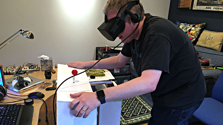
Jeremy Williams built PinSim, a cabinet controller for virtual reality pinball to get much more realistic game playing experience.
Jeremy, a huge pinball enthusiast, knew he had to build a cabinet when he saw Pinball FX 2 VR at Oculus Days. Digital pinball games have been around for quite a while, but as Jeremy noted, one of the problems with them is that your perspective is static. Virtual reality (VR) pinball games allows users to change their perspective while playing, allowing for more finesse.
The PinSim cabinet improves the game play experience by adding a few elements that are crucial for realistic pinball play such as tactile controls, “non-clicky” buttons for the flippers, and an accelerometer-based nudge system. Not only can you nudge the cabinet to move the ball, but if you nudge too much, you’ll tilt.
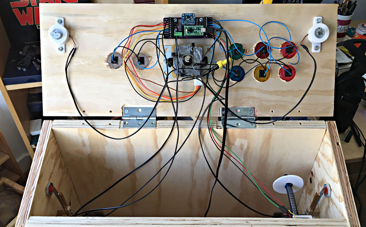
For the electronics a Teensy-LC using the MSF-XINPUT library by Zack Littell is used to emulate an Xbox 360 gamepad.
Build instructions for the cabinet can be found over on Tested. Code for the project can be found on GitHub. Over on the forum there’s a thread helping a user get all the libraries need to compile the PinSim code.
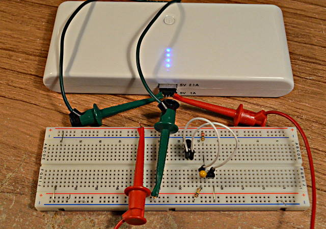
I purchased a cheap USB power pack, thinking it would be ideal for powering small projects. But it automatically shuts off if the device isn’t drawing a lot of power, since it’s meant for charging cell phones.
Here’s a 2 transistor circuit that keeps it on with very little battery drain by using brief pulses.
I wish I would have thought of this idea, but it came from this forum post by “Jp3141”. The battery pack automatically turns off if it doesn’t see a high current draw. But drawing a high current for only a brief time is enough to keep its internal timer going.
First, I did some experimenting and found a 22 ohm resistor keeps the power on indefinitely. A 27 ohm resistor kept it on for 19 seconds. With no load, it stays on for only 13 seconds. So a 22 ohm load it is!
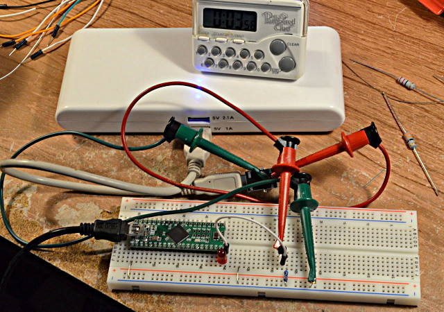
Just connecting a 22 ohm resistor to the 5 volt power is a pretty heavy load that would drain the battery. A 22 ohm resistor also burns about 1.1 watts, so it gets HOT. But the load doesn’t need to be on most of the time. The next step was connecting a Teensy and transistor circuit to turn on the load under software control.
Here the 5V pin drives a LED in series with a NPN base-emitter junction, to apply about 2.3 volts to a 10 ohm resistor. Of course, the NPN transistor has high current gain, so most of the 230 mA that flows through the 10 ohm resistor comes from the battery through the collector.
A little experimenting determined pretty quickly that pulses in the 8 to 10 ms range usually keep the battery pack on, but it sometimes turns off after a couple minutes. 20 ms seems very stable.
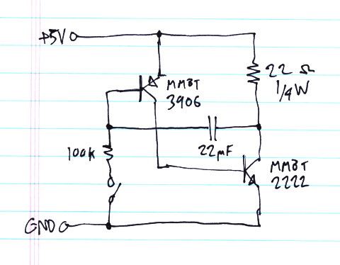
Knowing 20 ms is needed, I switched from using the Teensy++ to this simple 2 transistor oscillator:
A quick napkin calculation seemed to suggest this would need a really large capacitor. But with a little fiddling, it turned out 22 uF was enough. This circuit creates a pulse slight over 20 ms approximately every 1.4 seconds.
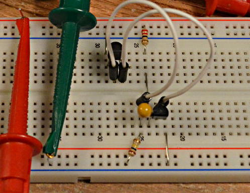
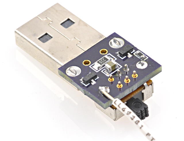
Here’s another close-up of the circuit on the breadboard. Just 2 transistors, 1 capacitor, and 2 resistors.
I let this run for about half an hour, with the battery pack happily remaining on the whole time.
The average battery current is ~3.5 mA.
While the transistors are on, the current is approx 222 mA (4.9V on 22 ohms). But the duty cycle is about 1.6%.
Inside the pack, a switching power supply is running to step up the batteries from 3.7 to 5 volts, and it’s powering those 4 blue LEDs. The internal stuff inside the pack probably wastes a lot more than only 3.5 mA.
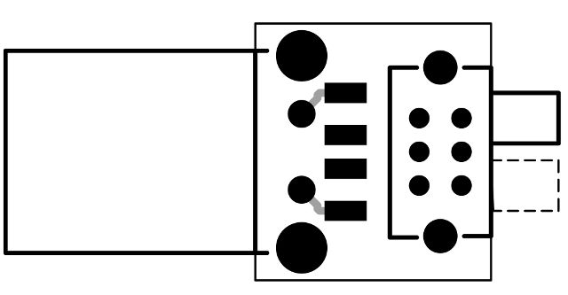
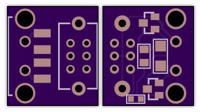
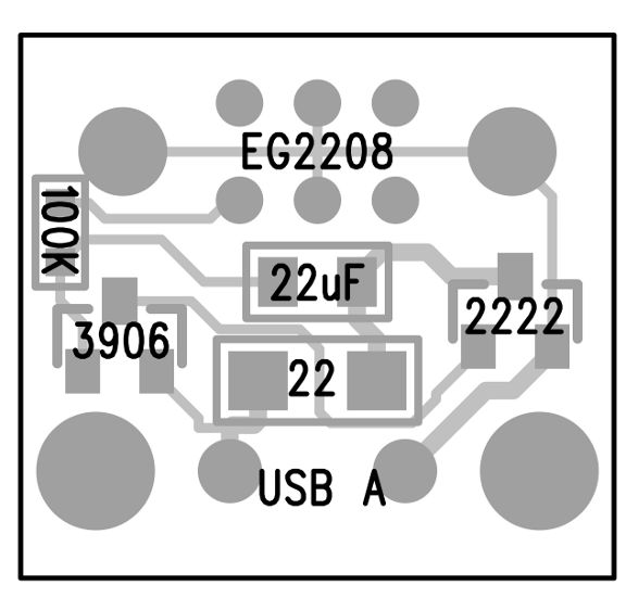
Of course, then I did a quick PCB layout. I added a switch in series with the 100K resistor, so it can be left plugged in and turned off to allow the battery pack to shut itself off. It’s a tiny board, only about the size of the USB connector itself.
I sent the files in to OSH Park. Here’s their preview.
Here’s the board on their site, if anyone else wants to build this:
If you need to tune the timing for a different battery pack, increasing the capacitor makes the pulse wider and lengthens the time between pulses. Decreasing the 100K resistor makes the pulse occur more frequently, without changing the width of the pulse.
EDIT: My battery pack turned off a couple times times after many minutes. I increased the capacitor to 47 uF and it ran for an hour. 22 uF might be a little on the low side? If you build this circuit, a little tweaking on the capacitor or resistor values might be needed if your battery pack is different.
EDIT AGAIN: Later I purchased an identical-looking battery pack, except it had black plastic instead of white. It turned out to have a completely different power detecting scheme. The pulses wouldn’t work. This little circuit clearly doesn’t apply to every battery pack, but it worked very well on the earlier white one.
This article was originally published on the DorkbotPDX website, on November 5, 2013. In late 2018, DorkbotPDX removed its blog section. An archive of the original article is still available on the Internet Archive. I am republishing this article here, so anyone still using these battery packs can try this circuit.
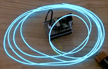
Years ago I experimented with shifting the color of El Wire by changing the AC frequency.
The color effect is subtle, but can be seen by most people with good color vision.
Not long after I published this video, I discovered “dcroy” built this same thing a few months before I did, and using only a 555 timer! Looks like it’s not as unique as I thought!
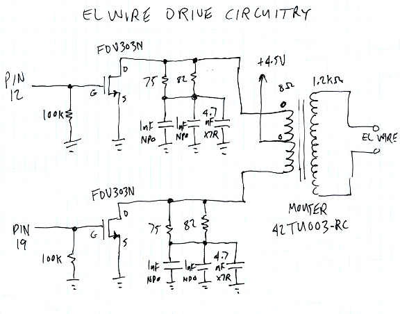
This is the schematic for the circuit I built. Most of the parts are small surface mount and they’re hidden under the transformer.
Here’s the code from the Arduino IDE. Pretty simple stuff. But beware, if you try this, it’s essential to drive each transistor for the same length of time, and not more than about 1ms. If you drive one more than the other, or leave either on too long, the transform sees a DC or low frequency signal. That could result in far too much current, probably destroying the transistors if the battery is fresh.
const int pin1 = 12;
const int pin2 = 19;

void setup() {
  Serial.end();  // USB off, to save power
  for (byte i=0; i<25; i++) {
    pinMode(i, OUTPUT);    // all unused pins low
    digitalWrite(i, LOW);  // to avoid wasting power
  }
  pinMode(pin1, OUTPUT);
  pinMode(pin2, OUTPUT);
}

unsigned int us = 250 * 64;
const int usMax = 500 * 32;
const int usMin = 120 * 32;
byte dir = 0;

void loop() {
  digitalWrite(pin1, HIGH);
  delayMicroseconds(us / 32);
  digitalWrite(pin1, LOW);
  if (dir) {
    us = us + 1 + us / 2048;
    if (us >= usMax) dir = 0;
  } else {
    us = us - 1 - us / 2048;
    if (us <= usMin) dir = 1;
  }
  digitalWrite(pin2, HIGH);
  delayMicroseconds(us / 32);
  digitalWrite(pin2, LOW);
}
This article was originally published on the DorkbotPDX website, on July 12, 2011. In late 2018, DorkbotPDX removed its blog section. An archive of the original article is still available on the Internet Archive. I am republishing this article here, in case anyone might wish to try El Wire color changing. Admittedly, El Wire became less popular around 2013 when inexpensive LED strips appeared on the market, but it still offers interesting effects which are hard to accomplish with LEDs.
Years ago, several “short” talks at a hackerspace that went far beyond their allotted time inspired me to make this nice countdown timer.
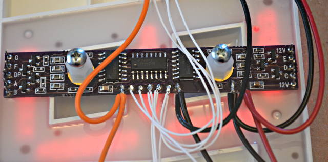
I found these 4 inch 7 segment displays cheap on Ebay, made a little constant-current driver board, and put it all together into a simple project.
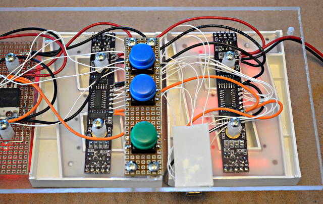
Here’s what the back side looks like, with buttons to control the countdown.
The green buttons starts & stops the countdown. The 2 blue buttons add or subtract 1 minute. It’s a very simple and minimal user interface!
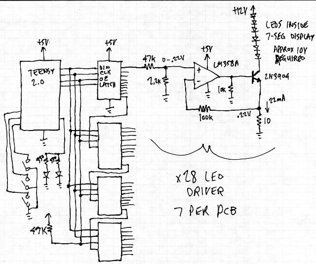
Here’s a rough schematic for the whole project. Well, except I left off the 7805 regulator and maybe some other mundane stuff, but this is pretty close.
The main challenge was driving the LEDs with a constant current, because they need about 10.5 volts across the several series LEDs. I wanted to run from 12 volts, so there wasn’t much voltage left over for the normal current limiting resistors. Instead, I used this opamp circuit.
(edit: opps, I wrote LM358A on the schematic, but it’s actually a LM324A opamp. Really, they’re the same, just 2 vs 4 per package… so you could use either if you try to build this on your own board, but if you use the PCB files below, get a 14 pin LM324A opamps)
The project runs from a Teensy 2.0. The code is very simple, using the SPI and Bounce libraries for the hardware interfacing.
The 7 segment displays were something I’d purchased from an E-bay merchant about a year ago. I can’t find then anymore (at least not for low prices), which is sad because they were really cheap at the time.
I actually created this PCB only days after the last Dorkbot open mic meetup (where talks went way beyond allotted time). Here’s a photo of the board.
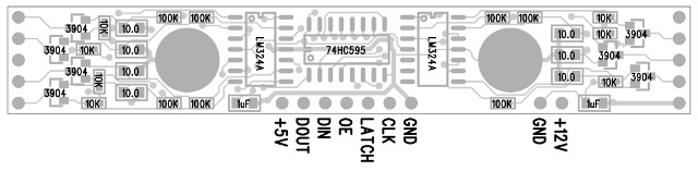
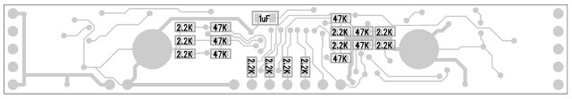
There’s actually quite a few parts on the board. Here are the placement diagrams:
If you find any of these awesome 4 inch displays, hopefully this little board will come in handy for driving them efficiently with only 12 volts.
This article was originally published on the DorkbotPDX website, on March 22, 2013. In late 2018, DorkbotPDX removed its blog section. An archive of the original article is still available on the Internet Archive. I am republishing this article here, in the hope it may continue to be found and used by anyone interested in these 7 segment displays.