Years ago, several “short” talks at a hackerspace that went far beyond their allotted time inspired me to make this nice countdown timer.

I found these 4 inch 7 segment displays cheap on Ebay, made a little constant-current driver board, and put it all together into a simple project.
Here’s what the back side looks like, with buttons to control the countdown.
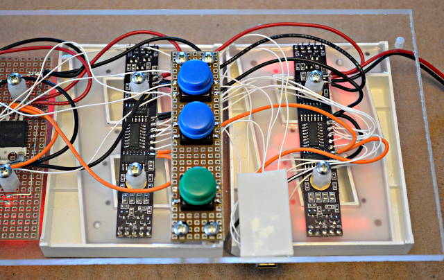
The green buttons starts & stops the countdown. The 2 blue buttons add or subtract 1 minute. It’s a very simple and minimal user interface!
Here’s a rough schematic for the whole project. Well, except I left off the 7805 regulator and maybe some other mundane stuff, but this is pretty close.
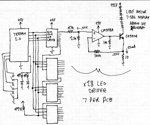
The main challenge was driving the LEDs with a constant current, because they need about 10.5 volts across the several series LEDs. I wanted to run from 12 volts, so there wasn’t much voltage left over for the normal current limiting resistors. Instead, I used this opamp circuit.
(edit: opps, I wrote LM358A on the schematic, but it’s actually a LM324A opamp. Really, they’re the same, just 2 vs 4 per package… so you could use either if you try to build this on your own board, but if you use the PCB files below, get a 14 pin LM324A opamps)
The project runs from a Teensy 2.0. The code is very simple, using the SPI and Bounce libraries for the hardware interfacing.
#include <SPI.h>
#include <Bounce.h>

// pins
//  0 - Latch
//  1 - Clock
//  2 - Data
//  4 - Enable (low=on)
//  9 - Dots (high=on)

Bounce button1 = Bounce(10, 12);
Bounce button2 = Bounce(23, 12);
Bounce button3 = Bounce(22, 12);

uint8_t min=5;
uint8_t sec=0;
uint8_t unused_pins[] = {3,5,6,7,8,11,12,13,14,15,16,17,18,19,20,21,24};

void setup()
{
	for (uint8_t i=0; i < sizeof(unused_pins); i++) {
		pinMode(i, OUTPUT);
		digitalWrite(i, LOW);
	}
	pinMode(10, INPUT_PULLUP);
	PORTC |= 0x80;
	pinMode(22, INPUT_PULLUP);
	pinMode(23, INPUT_PULLUP);
	digitalWrite(4, HIGH);
	pinMode(0, OUTPUT);
	pinMode(1, OUTPUT);
	pinMode(2, OUTPUT);
	pinMode(4, OUTPUT);
	pinMode(9, OUTPUT);
	digitalWrite(0, LOW);
	digitalWrite(1, LOW);
	digitalWrite(2, LOW);
	digitalWrite(4, HIGH);
	digitalWrite(9, LOW);
	SPI.begin();
	update();
}

uint8_t sevenseg[10] = {
	// gfedcba
	0b00111111, //  aaa
	0b00000110, // f   b
	0b01011011, // f   b
	0b01001111, //  ggg
	0b01100110, // e   c
	0b01101101, // e   c
	0b01111101, //  ddd
	0b00000111,
	0b01111111,
	0b01101111
};

void update(void)
{
	if (min > 99) min == 99;
	if (sec > 59) sec = 59;
	SPI.transfer(min >= 10 ? sevenseg[min/10] : 0);
	SPI.transfer(min > 0 ? sevenseg[min%10] : 0);
	SPI.transfer(sevenseg[sec/10]);
	SPI.transfer(sevenseg[sec%10]);
	delayMicroseconds(2);
	digitalWrite(0, LOW);
	delayMicroseconds(2);
	digitalWrite(0, HIGH);
	digitalWrite(9, HIGH);
	digitalWrite(4, LOW);
	delayMicroseconds(5);
	digitalWrite(0, LOW);
}

elapsedMillis count = 0;
uint8_t running = 0;

void loop()
{
	button1.update();
	button2.update();
	button3.update();
	if (button1.fallingEdge()) {
		Serial.println("button1 - Start/Stop");
		if (running) {
			running = 0;
		} else {
			running = 1;
			count = 750;
		}
	}
	if (button2.fallingEdge()) {
		Serial.println("button2 - Add 1 minute");
		if (min < 99) {
			min++;
			update();
		}
	}
	if (button3.fallingEdge()) {
		Serial.println("button3 - Subtract 1 minute");
		if (min > 0) {
			min--;
		} else {
			sec = 0;
			running = 0;
		}
		update();
	}

	if (running && count >= 1000) {
		count -= 1000;
		if (sec > 0) {
			sec--;
		} else {
			if (min > 0) {
				min--;
				sec = 59;
			} else {
				running = 0;
			}
		}
		update();
	}
}
The 7 segment displays were something I’d purchased from an E-bay merchant about a year ago. I can’t find then anymore (at least not for low prices), which is sad because they were really cheap at the time.
I actually created this PCB only days after the last Dorkbot open mic meetup (where talks went way beyond allotted time). Here’s a photo of the board.
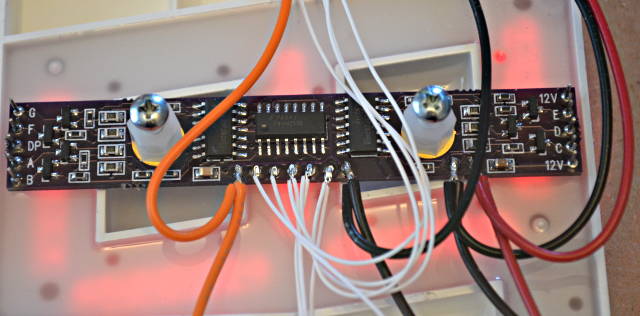
There’s actually quite a few parts on the board. Here are the placement diagrams:
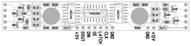
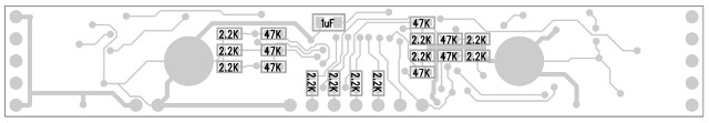
The circuit board can be ordered from OSH Park, or you can download the original gerber files if you’d like to have them made elsewhere.
If you find any of these awesome 4 inch displays, hopefully this little board will come in handy for driving them efficiently with only 12 volts.
This article was originally published on the DorkbotPDX website, on March 22, 2013. In late 2018, DorkbotPDX removed its blog section. An archive of the original article is still available on the Internet Archive. I am republishing this article here, in the hope it may continue to be found and used by anyone interested in these 7 segment displays.