Teensyduino 1.43 Released

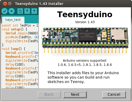
Today PJRC is releasing Teensyduino version 1.43.

The 1.43 installers are available now at the downloads page.

Arduino 1.8.6 Support

The main new feature in 1.43 is support for Arduino 1.8.6.  The main reason to upgrade is 1.8.6 can compile your code significantly faster.

Arduino 1.8.6 is the first non-beta Arduino IDE to support parallel compile.  If your computer has a quad-core processor, when rebuilding all files, Arduino may compile up to 4 pieces of code at the same time.  Usually the speed increase is much less than 4 times faster, but still it manages to compile code in much less time than running every compiler process 1 at a time.

When you change boards or settings, a full rebuild of all libraries files must be done for all library files your code uses.  Arduino 1.8.2 to 1.8.5 would often do this full rebuild unnecessarily, especially if you edited any of the library files (not in the Arduino IDE’s editor).  1.8.6 fixes this unnecessary rebuilding.

However, not everything is perfect with 1.8.6.  Several bugs were discovered after release which cause 1.8.6 to crash, especially if certain data files are corrupted.  Teensyduino 1.43 includes fixes for a couple of these bugs.  The rest will be fixed in Arduino 1.8.7, which may appear soon.  When it does, of course we’ll release Teensyduino 1.44 to support it.

Headless Install

The installer now support a “headless” command line install.  This can be useful if you wish to create scripts to automatically install Teensyduino.  The main intended use is for Continuous Integration testing with systems such as Travis-CI.

Run the installer with –dir=<directory> to specify the Arduino install location.  Using this option cases the installer to run automatically without the GUI.

Adafruit has offered to include Teensy in their automated testing script.  Soon this will allow Teensy to be automatically tested (at least to verify libraries compile without error) for all of Adafruit’s libraries!

Bugs Fixed

Several issues are fixed in version 1.43.

  • Fix default Ethernet CS pins on Teensy 2.0 & Teensy++ 2.0.  Old versions of Ethernet would default to the “SS” pin on AVR chips, and if you wanted any other pin your only option was to edit the Ethernet library code!  With the addition of Ethernet.init(pin), you could choose which pin to use, but this change also caused the default to become pin 10, even if SS was a different pin on your board (as it is with Teensy 2.0 & Teensy++ 2.0).  Now the default is restored to the actual SS pin, and you can use Ethernet.init(pin).
  • Fix USB Keyboard ‘#’ for UK & Irish layouts.
  • Generic UDP class support beginMulticast.  Some libraries using multicast need this defined in the board’s core library.
  • Fix USB MIDI hogging transmit buffers.  If you used USB MIDI together with USB Serial or other USB communication, and you transmit USB MIDI messages faster than your computer can process, previously the MIDI message could consume all the USB buffer memory.  This fix prevents MIDI from hogging all the buffers, so the other non-MIDI communication (hopefully) will not stall.
  • Fix FreqCount for use at high frequencies.  A bug which caused very infrequent errors when measuring very high frequencies has been fixed.
  • Fix SerialPlotter for Ports(Teensy).  Previously Arduino’s Serial Plotter would only work if you had selected Tools > Ports from the “Serial” section of the menu.  Now the “Teensy” ports section is fully supported.  When using a “Teensy” port, board disconnect and reconnect are supported.  The plot restarts from zero when you plug the cable in.  Proper stop and restart is also supported when you upload new code.
  • USBHost_t36 fix for Gigabyte keyboard (thanks KurtE).  These special gaming keyboards with “N Key Rollover” should now work.
  • OctoWS2811 update movie2serial.pde for compatibility with Processing 3.4.  This program streams video to large LED projects.  Minor updates were needed to work with the newest version of Processing and its video library.
  • Remove BYTE define.  This was previously included in Teensyduino for pre-1.0 Arduino compatibility.  But some libraries and code tend to use “BYTE” for their own constants and variables, causing a conflict.  This feature for compatibility with ancient Arduino libraries was causing more harm than good.  It’s been removed.
  • Update WS2812Serial documentation.  A mistake in the documentation showed an extra pin, which was never actually supported and can’t work due to hardware limitation.
  • Improve installer help dialog on Windows.  The “Windows App” incompatible with Teensyduino.  The installer now mentions this in the “?” help dialog.
  • Workaround a rare USB buffering issue.  During sustained fast data transfer from a PC to Teensy, a rare bug could cause wrong data to be received after many megabytes of transfer.  A workaround was added to prevent this problem.  Special thanks to Trammell Hudson for providing a test case.
  • Fix for Arduino 1.8.6 startup (Arduino issue #7917).  If any library you have installed has a version number which Arduino 1.8.6 can’t understand, the IDE crashes at startup.  A fix for this problem is included, so you aren’t left with the software unable to run if you have a “bad” library installed.
  • Add Arduino’s fix for slow 1.8.6 menus on Mac (Arduino issue #7935).  Newer versions of Java on Macintosh are much slower to create menus.  The Arduino developers worked around this problem by creating the menus only once, and they’re merely modified when changes are needed.  Teensyduino 1.43 adds this fix to your copy of 1.8.6.


Arduino Ethernet Library 2.0.0

Today I released the Arduino Ethernet Library version 2.0.0, for all Arduino boards (not just Teensy).

Version 2.0.0 adds many new features and greatly improves performance.  Here’s a detailed look at what’s new.

Auto-Detect Hardware

All 3 SPI-based chips from Wiznet, W5100, W5200, and W5500 are supported.  Ethernet.begin() automatically detects which chip you have connected.

The chip detection process uses the Wiznet software reset command followed by 2 write and read-to-verify checks on the main configuration register, for very robust hardware detection.

Ethernet.init(cspin), an extension added in Adafruit’s Ethernet2 library, is also supported, so you can use any digital pin for the CS signal.

Performance Improvement

Version 2.0.0 greatly improves performance.  Optimizations at multiple levels within the library work together to vastly improve performance, especially on the oldest W5100 hardware, and also make the most of the newer W5200 and W5500 chips.

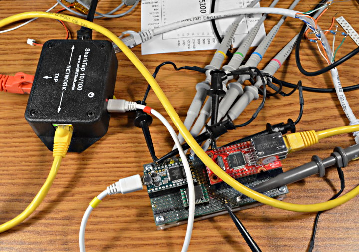
A a tremendous amount of work went into these optimizations.  In this photo you can see the setup for debugging timing issues with WIZ812MJ (W5100) and Teensy 3.2, using a 4 channel oscilloscope to monitor SPI communication and an active network tap to monitor the Ethernet packets.

The 2.0.0 performance optimizations are performed on 6 levels.  Here are details, from the highest to the lowest level.

1: Caching Socket Registers

The Wiznet chips transmit and receive Ethernet packets with their internal buffer memory.  Each socket’s buffers are managed using several 16 bit pointer registers within the chip.  Previously these registers would be read and sometimes updated for every access, using many bytes of SPI communication, even just to check whether data is available.

A small amount of memory on the Arduino side is used to cache these registers, which greatly reduces non-data SPI communication.

2: Immediate TCP ACK

By default the Wiznet chips have a feature to delay sending TCP ACK packets.  For simple programs which read 1 byte at a time, this makes good sense, since you wouldn’t want to transmit a flood of ACK packets for every single received byte.

The socket register caching also allows the number of Sock_RECV commands written to the chip to be greatly reduced, even for simple Arduino sketches which read 1 byte at a time.  This allows Ethernet 2.0.0 to control the timing of ACK packets, immediately when the Sock_RECV command is used to update the chip’s buffer pointers.

W5100 chips see a tremendous TCP speed boost, because the delayed ACK feature was poorly implemented in that old chip.  Even W5200 & W5500 speed is improved, especially when larger buffers are used.

3: Block Mode For Data Transfer

All SPI commands have overhead, 3 bytes on W5100 & W5500, 4 bytes on W5200, before actually communicating data.  On W5200 & W5500, after suffering this overhead, “block mode” allows many bytes can be transferred using a single command.

When your Arduino sketch reads or writes multiple bytes, these efficient block mode commands are used.  Other libraries, like Adafruit & Seeed Studios Ethernet2 have used this block mode for data transfer.

4: Block Mode For Registers

Unlike other libraries for W5200 or W5500, the efficient block most is also used with accessing 16 and 32 bit registers.  In addition to nearly cutting the register access time in half (and register access is done much less often due to caching), block mode also greatly reduces the chances that a register which may change will being read will need to be accessed more than twice to get the same value.

5: SPI Block Transfer

The SPI library has a block transfer function which is optimized to reduce delays between bytes on the SPI bus.  W5200 & W5500 now leverage SPI.transfer(buffer, size) for a significant speed increase when used with boards having a SPI library which optimizes this function.

6: Native CS Pin Control

Control of the CS pin in version 1.1 was done using hard-coded register access to pin 10.  While very efficient, only certain boards were supported and using any other pin required editing the library.

Version 2.0.0 allows any digital pin, but still uses efficient access to GPIO registers on most boards.  All AVR, SAMD, SAM (Arduino Due), PIC32, Teensy and ESP32 boards are supported.  On others, the CS pin control uses ordinary digitalWrite.

Client Functions

EthernetClient has 3 new functions similar to the ones from EthernetUDP.  The remoteIP() function is very nice after connecting, if you used a name and DNS found the IP number.

remoteIP()
localPort()
remotePort()

Timeout Control

When things don’t go as expected, the default timeouts can be quite lengthy.  Especially when communicating on with local devices on the same LAN, you might like much shorter timeouts.

Ethernet.setRetransmissionTimeout(milliseconds)
Ethernet.setRetransmissionCount(number)
client setConnectionTimeout(milliseconds)

The connection timeout is how long to wait when trying to connect to a server, or for stop() to wait for the remote host to disconnect.

Server Functions

EthernetServer now has an accept() function, for use by more advanced projects.  The traditional available() function would only tell you of a new client after it sent data, which makes some protocols like FTP impossible to properly implement.

The intention is programs will use either available() or accept(), but not both.  With available(), the client connection continues to be managed by EthernetServer.  You don’t need to keep a client object, since calling available() will give you whatever client has sent data.  Simple servers can be written with very little code using available().

With accept(), EthernetServer gives you the client only once, regardless of whether it has sent any data.  You must keep track of the connected clients.  This requires more code, but you gain more control.

EthernetServer now also has a boolean test, which tells you whether the server is listening for new clients.  You can use this to detect whether EthernetServer begin() was successful.  It can also tell you when no more sockets are available to listen for more clients, because the maximum number have connected.

Hardware Status

Version 2.0.0 adds two functions to help you diagnose hardware issues.

Ethernet.hardwareStatus() tells you which Wiznet chip was detected during Ethernet.begin(), if any.  When “nothing works” this can help you discover whether your Ethernet shield hardware is good and you should check for networking issues, or if you need to work on the hardware first.

Ethernet.linkStatus() on W5200 and W5500 tells you whether the link is active.  Sometimes things don’t work only because a cable is unplugged.

All the examples updated have been updated to use these, for better troubleshooting.

Direct Settings Control

Now you can access the network settings after Ethernet.begin().  These are meant to be used in manual configuration mode, not with DHCP.

Ethernet.setMACAddress()
Ethernet.setLocalIP()
Ethernet.setSubnetMask()
Ethernet.setGatewayIP()
Ethernet.setDnsServerIP()
Ethernet.MACAddress()
Ethernet.localIP()
Ethernet.subnetMask()
Ethernet.gatewayIP()
Ethernet.dnsServerIP()

Boards Tested

I attempted to test Ethernet 2.0.0 with as many boards as possible.

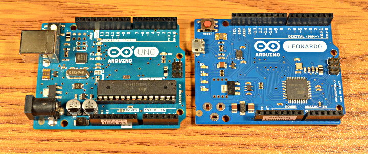
Arduino Uno R3 and Arduino Leonardo

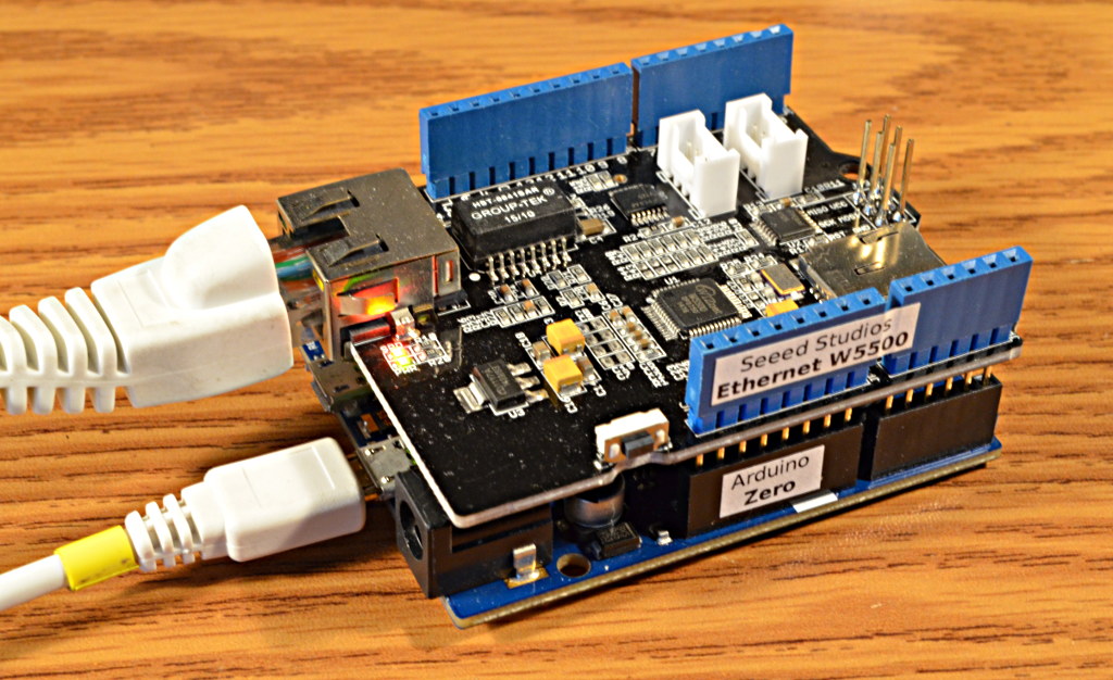
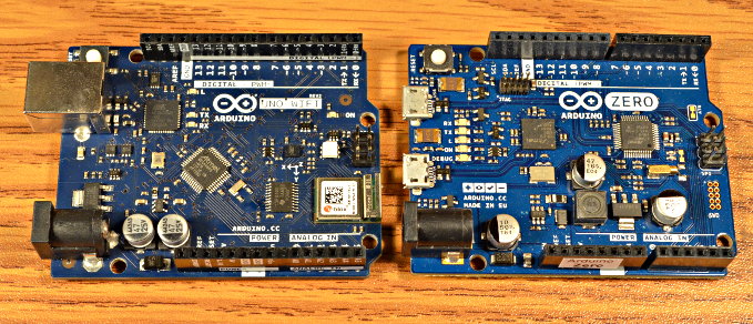
Arduino Uno Wifi Rev2 (pre-release sample) and Arduino Zero

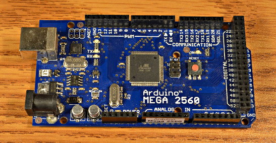
Arduino Mega 2560 (counterfeit/clone – sorry Massimo…)

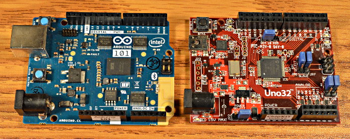
Arduino 101 Intel Curie and ChipKit Uno32

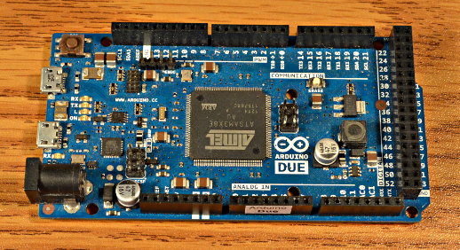
Arduino Due

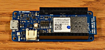
Arduino MRK1000

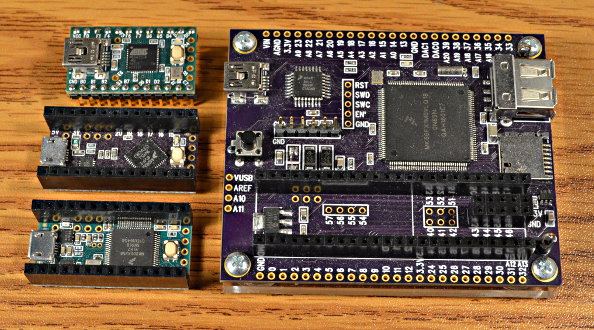
Teensy 2.0, Teensy LC, Teensy 3.2, and Teensy 3.6 Reference Board

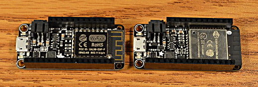
Adafruit Huzzah ESP8266 Feather and Huzzah32 ESP32 Feather

Shields Tested

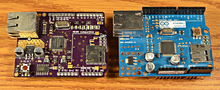
Arduino Ethernet R2 (hand soldered) and Arduino Ethernet R3

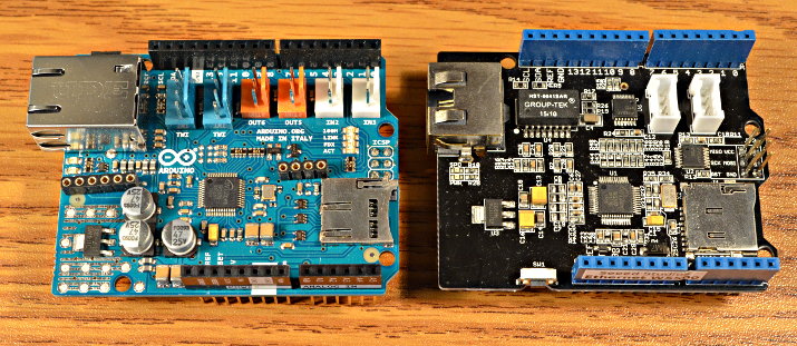
Arduino.org Ethernet2 and Seeed Studios W5500 Ethernet

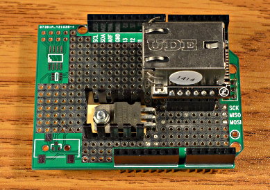
Wiznet WIZ820io on hand-soldered protoboard adaptor

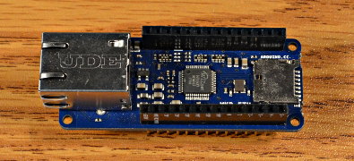
Arduino MRK ETH (pre-release sample)

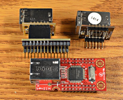
Wiznet WIZ850io with Teensy adaptor, WIZ820io, and WIZ812MJ.

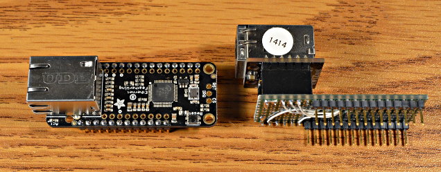
Adafruit FeatherWing Ethernet and WIZ820io with MKR adaptor

ESP8266 SPI library requires issue #2677 fixed – transfer(buffer, size)

ESP32 SPI library requires issue #1623 fixed – transfer(buffer, size)

Benchmarks & Test Results

Four tests were run on every board+shield tested.

WebClient (local) is a copy of the WebClient example, modified to access a Linux web server on the same LAN, where packets have only the latency of a layer2 Ethernet switch, less than 0.1 ms.  This test primarily measures the SPI communication speed and CPU overhead.  Well optimized SPI library code greatly impacts this test.  Numbers below are in kbytes/sec.  If you care about LAN-connected speeds, and your hardware is capable of higher SPI clock speeds, editing w5100.h can greatly increase this performance.

WebClient (google) is the WebClient example without any changes.  In this test, packets have approximately 7 ms latency.  This test measures how well the TCP communication works with Internet latency.  Numbers below are in kbytes/sec.  These numbers vary considerably.  The test was run 4 times on each board with the highest speed recorded.  YMMV!  If you care about Internet-connected speeds, editing Ethernet.h for fewer sockets and larger buffers can increase this performance.

UdpNtpClient tests UDP networking.  This example was run and 3 responses from the NTP time server was considered passing the test.

WebServer tests the EthernetServer functionality.  This example was run and a browser on a computer connected to the local network was used to access the analog readings info 3 times.

Board                   Shield                  WebClient       WebClient       UdpNtpClient    WebServer
                                                (local)         (google)

-- larger numbers = faster data transfer --

Arduino Uno R3          Arduino Ethernet R2     82.66           79.27           ok              ok
                        Arduino Ethernet R3     82.66           79.11           ok              ok
                        WIZ820io                331.27          191.85          ok              ok
                        Arduino.org Ethernet2   329.60          195.32          ok              ok
                        Seeed Ethernet W5500    329.00          185.44          ok              ok

Arduino Leonardo        Arduino Ethernet R2     82.28           78.75           ok              ok
                        WIZ820io                330.30          183.69          ok              ok
                        Seeed Ethernet W5500    328.14          179.98          ok              ok

Arduino Uno Wifi Rev2   Arduino Ethernet R2     72.30           69.55           ok              ok
                        Arduino Ethernet R3     72.23           69.50           ok              ok
                        WIZ820io                212.19          161.94          ok              ok
                        Arduino.org Ethernet2   212.88          169.72          ok              ok (linkstatus wrong)
                        Seeed Ethernet W5500    213.36          163.86          ok              ok (linkstatus wrong)

Arduino Mega 2560       Arduino Ethernet R2     77.44           74.31           ok              ok
                        WIZ820io                325.44          172.73          ok              ok
                        Seeed Ethernet W5500    323.36          179.58          ok              ok

Arduino Zero            Arduino Ethernet R2     96.64           91.42           ok              ok
                        Arduino Ethernet R3     96.64           91.33           ok              ok
                        WIZ820io                298.53          177.53          ok              ok
                        Arduino.org Ethernet2   305.28          181.60          ok              ok
                        Seeed Ethernet W5500    305.26          183.13          ok              ok

Arduino Due             Arduino Ethernet R3     109.73          105.98          ok              ok
                        WIZ820io                670.88          206.51          ok              ok
                        Seeed Ethernet W5500    689.69          214.44          ok              ok

Arduino 101 (Intel)     Arduino Ethernet R3     43.60           42.39           ok              ok
                        WIZ820io                349.35          169.37          ok              ok
                        Seeed Ethernet W5500    359.32          168.96          ok              ok

Arduino MKR1000         MRK ETH                 298.93          181.27          ok              ok
                        WIZ820io                291.98          125.20          ok              ok

Teensy 3.6              WIZ850io                1143.58         212.59          ok              ok
                        WIZ820io                1102.71         202.44          ok              ok
                        WIZ812MJ                274.14          180.76          ok              ok

Teensy 3.2              WIZ850io                958.06          205.37          ok              ok
                        WIZ820io                914.78          215.44          ok              ok
                        WIZ812MJ                234.55          170.07          ok              ok

Teensy LC               WIZ850io                479.73          200.51          ok              ok
                        WIZ820io                471.95          199.62          ok              ok
                        WIZ812MJ                137.77          126.40          ok              ok

Teensy 2.0              WIZ812MJ                84.85           81.07           ok              ok

ChipKit Uno32           Arduino Ethernet R2     272.18          159.72          ok              ok
                        WIZ820io                837.56          188.31          ok              ok
                        Seeed Ethernet W5500    858.81          177.19          ok              ok

Adafruit ESP8266        FeatherWing Ethernet    583.31          fail (dns)      fail (dns)      ok

Adafruit ESP32          FeatherWing Ethernet    965.76          211.06          ok              ok


Possible issues:
Adafruit ESP8266 fails WebClient (google) and UdpNtpClient tests, due to DNS
Arduino Uno R3 with WIZ820io running WebClient sometimes fails to connect to google
Arduino Due with WIZ820io running WebClient sometimes fails to connect to google
Arduino Uno Wifi Rev2 with WIZ820io running WebClient sometimes fails to connect to google
Arduino Mega 2560 with WIZ820io running WebClient sometimes fails to connect to google

Near-Term Plans

Not everything I wanted to accomplish made the 2.0.0 release.  These are changes I would like to make “soon”…

DNS on ESP8266 appears to be broken.  Help wanted!  Hopefully someone from the ESP community can look at this.  Or at least point me to a board that uploads faster and has a working Ethernet shield!  (nearly all ESP boards in Arduino form factor lack the 6 pin SPI header)

Non-blocking DHCP & DNS are needed for projects needing to keep rapid polling of other I/O.

DHCP could use improvements: set hostname, better handling of error conditions, disable when settings overridden by manual settings.

Farther Future Plans

In the distant future (and a dream world where I have many more hours in every day), I’d like to do much more with Ethernet.

Small writes could be combined and sent as single packets, if we had a timeout infrastructure or scheduler available.

DNS probably should migrate to Arduino core library, so it can shared among different networking libraries.

DNS cache should be implemented, at least with 1 entry, so we don’t repetitively look up the same host’s IP number.

Wiznet chips have an interrupt pin, which is currently unused.   On high-end boards, we could allocated buffers in RAM and read data earlier, to allow faster TCP speeds over high latency networks.

Someday I’d love to integrate EventResponder

But here & now, this 2.0.0 brings a much-needed features and a huge improvement in performance to all Arduino users!

Teensyduino 1.42 – What’s New

Today PJRC is releasing Teensyduino version 1.42.

Here’s a detailed look at 1.42’s many new features and improvements.

I’d like to thank everyone who contributed & beta tested, especially Defragster!

The 1.42 installers are available now at the downloads page.

Arduino IDE Ports Menu & Serial Monitor

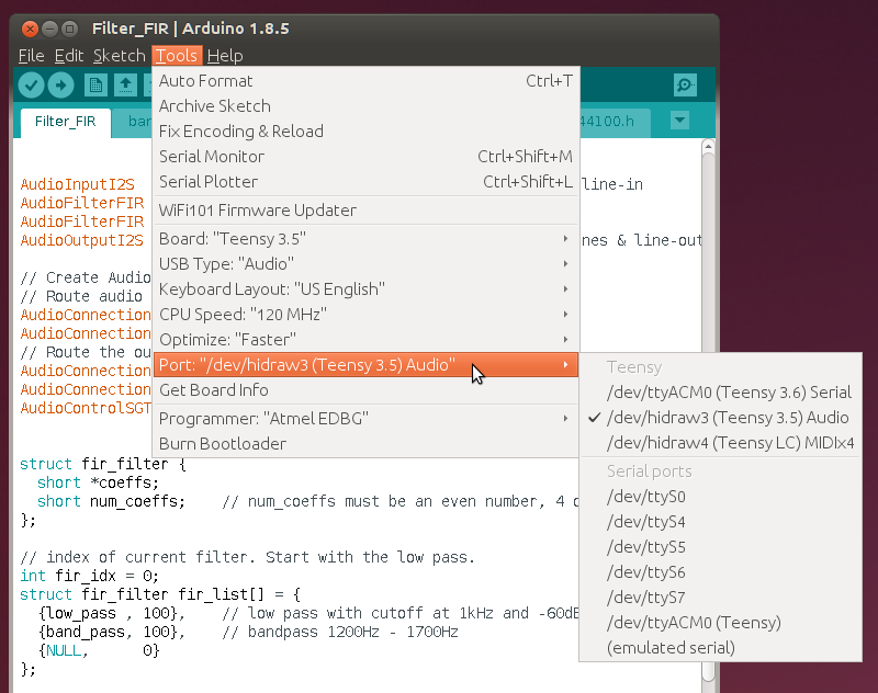
Since 2009 Teensy has supported non-Serial USB types (selected in the Tools > USB Type menu), but Arduino’s Ports menu has worked only with Serial devices.  1.42 extends the Ports menu with a new “Teensy” section capable of showing every USB type Teensy implements.

In this screenshot, 3 Teensy boards are connected, but only 1 is programmed to be Serial.

Teensyduino’s non-Serial modes include a HID interface to emulate serial, so you can still use Serial.print() to the Arduino Serial Monitor.  Arduino’s “Serial ports” list is still present, where you would select “(emulated serial)” to use those other boards.  The new “Teensy” ports list allows you clearly see which boards are really connected and to precisely choose the one you want.

Selections from this new Teensy Ports list are based on the physical USB port, plus any USB hubs.  This info is shown in the lower right corner.

Here “usb2/2-1/2-1.2/2-1.2.2” is a Linux syntax meaning port 2 of a hub plugged into port 1 of the 2nd USB controller.  Similar codes are used on Windows and Macintosh.  These physical location codes allow Arduino to target exactly the board you’ve selected, even when it changes USB type.

Physical location allows Teensy auto-reboot to know exactly which Teensy you wish to upload.  Previously (and still if you don’t select from the Teensy ports list) attempting to reboot required searching and trying to reboot whatever boards were found.  If your Teensy isn’t responding to USB (interrupts disabled, deep sleep, etc) the auto-reboot process won’t search for other boards.  It ends quickly.  Of course no software on a PC or Mac can get your Teensy to report if it’s not communicating on the USB, which is why every Teensy is made with a button to force entering programming mode.

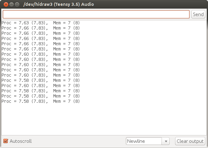
When you open the Arduino Serial Monitor with a board selected in the Teensy Ports list, a special version of the serial monitor customized to Teensy is used.

You can easily tell it apart from the normal serial monitor because it lacks the baud rate drop-down selection.  Teensy USB always communicates at full USB speed, not the serial baud rate.

This new serial monitor has many features you can’t easily see.  If you unplug your Teensy while it’s open, the USB disconnect is automatically detected.  Likewise, reconnecting (on the same physical USB port) is automatically detected.  Access to the hardware is done by a native “teensy_serialmon” helper program, rather than a Java serial library, which is meant to solve rare but difficult communication problems some people encounter.

If you want to use the old way, via the Java serial library, just select from the “Serial ports” part of the Ports menu.  Look for the baud rate drop-down list to confirm you’re using the traditional serial monitor.

256K RAM Usable on Teensy 3.5

Some NXP/Freescale’s documentation for the MK64FX512 chip used on Teensy 3.5 says 192K of RAM.  Other documentation says 256K.  We have recently confirmed all these chips really do have 256K RAM.

Teensyduino 1.42 enables access to all 256K, except the last 8 bytes.  Teensy Loader looks at the initial stack address to deduce which board you selected when compiling.  Future versions may improve how the intended board is communicated.  With 1.42, you get to 65528 more bytes of RAM for variables on Teensy 3.5.

USB Touchscreen Emulation

Many modern PCs have touchscreens, which is distinctly different then simply a mouse, because they can track the position of up to 10 fingers.

Starting with 1.42, Teensy can emulate a 10-finger tracking touchscreen.  This quick video demo shows how it works.

After installing 1.42, click File > Examples > Teensy > USB_Touchscreen > TenFingerCircle to open the example used in this video.

Windows, Linux and some Android systems support multi-touch screens.  Unfortunately no Apple Macintosh computers recognize USB multi-touch devices yet.

Audio Library New Features

Many great new features have been added to the Teensy Audio Library for 1.42.  For this article I had wanted to shoot video demos, but the time required would mean holding up the 1.42 release.  For now, here’s a quick summary with photos.  I hope to bring you another detailed article next week with more details.

Audio: FreeVerb

FreeVerb was added, in both mono and stereo.  It implements the high quality reverb algorithm as published by “Jezar” at Dreamport.  FreeVerb’s quality is better than the reverb effect contributed a couple years ago by Joao Rossi FIlho.  However, it uses more memory.  The stereo FreeVerb requires Teensy 3.5 or 3.6, due to RAM usage.

FreeVerb has 2 tunable parameters for “room size” and “damping” to give you control over the effect.  Of course, you can also add a mixer using the FreeVerb “wet” output with the original “dry” signal to tune how strongly the reverb effect is heard.

Audio: Granular Pitch Shift & Freeze

John-Mike of Bleep Labs contributed a granular processing effect.  In the freeze mode it repeatedly replays a short segment of the sound you recently heard.

Pitch shift mode captures grains continuously and plays them back windows overlapping, interpolated to a different speed.  When the parameters are set well, it results in a pretty good real-time pitch shift.  Of course you can also set the parameters not-so-well if you wish to hear a very grainy output!

Audio: Waveforms

The generic waveform synthesis was greatly improve for 1.42, inspired by Bleep Labs, though in the end new code was written.

Variable Triangle has been added to the waveform synthesis, which allows you to change continuously from a sawtooth to triangle.

A long-standing bug with the phase(angle) function has been fixed in 1.42.  You can now create 2 or more waveforms and control their relative phase shift.  Of course all of the waveforms work down to nearly zero, so any can be used as low frequency oscillators (LFOs) to control or sequence effects or other synthesis, now with full control over relative phase timing.

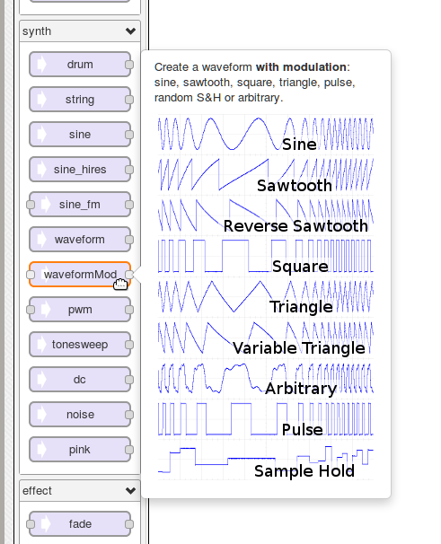
A new modulated waveform synthesis object has also been added.

Previously only Sine_FM offered modulation.  It was limited to one octave of frequency change, and the modulating signal varied the waveform period, which isn’t the proper “volt per octave” model.

The new waveform modulation allows you modulate the frequency of any of the 9 waveforms.  Up to 12 octaves are available (the range is configurable), allowing you to modulate even a sub-sonic LFO all the way up to the top of human hearing range!  The modulating signal uses proper exponential “volt per octave” scaling.

You can also configure the modulation to affect the waveform phase, for 8 of the 9 waveforms.  The amount of phase shifting is also configurable, up to 9000 degrees (±25 full waveform cycles).

Waveform modulation also has a 2nd input, to allow any signal to modulate the Pulse duty cycle and Variable Triangle waveform shape.

Audio: Pulse Density Modulated (PDM) Input

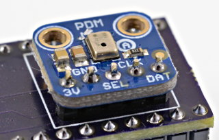
Some very low cost microphones have a special 1-wire pulse density output signal, which must be low-pass filtered to recover the audio signal.

Teensy now supports these PDM signals.  The low-pass filter is implemented as a single 512-tap FIR filter, which should have much better passband performance than the Cascaded Integrator Comb (CIC) filters typically used.  But this does come at a computation cost, approximately 39% CPU usage when running Teensy at 96 MHz.

Audio: Other Improvements

Support for the WM8731 codec chip has been improved, with the ability to properly select between its microphone vs line input.

The envelope effect now offers status functions to tell if it’s active, and whether its sustain period as ended.  When you use multiple envelopes to create (polyphonic) notes from oscillators or continuous other sound sources, these can help you better select which envelope is not currently “busy” to avoid truncating in-progress sounds.

The WAV file player and wav2sketch utility have been updated to handle unusual WAV files containing junk sections or other metadata before the format section.  Now you can use these WAV files without having to convert them.

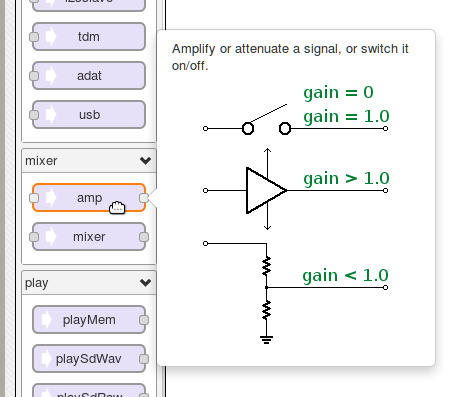
A simple “amp” object has been added, meant for switch signals, or amplifying or attenuating.

While this functionality has long been available by using only 1 channel of a mixer, consistent feedback from users has shown that placing a mixer into a graphical design simply does not feel right.  Of course, the amp implements the cases of gain=0 and gain=1.0 by skipping all the math for efficient switching of signals.

Updates have also been made to audio library documentation in the design tool (right side panel).  As the audio library continue to grow, documenting its many features well is becoming ever more important.

Compile Speedup

1.42 has changes to speed up fully recompiling your project.  When Arduino prints “Build options changed, rebuilding all”, you’ll still have to wait, but hopefully not nearly as long.

The main improvement comes from removing “#include <algorithm> from wiring.h”.  Version 1.41 brought a greatly improved map() function which automatically detects if the variable you’re translating is an integer or floating point number.  This magic depends on C++14 features, so wiring.h had this and other includes added.

It turns out nearly all of the extra compile time is due to that one #include <algorithm> header.  It has been removed, and map() still works, still automatically detecting integer versus floating point.

1.42 also changes the build process to use a pre-compiled header for Arduino.h (which in turn includes wiring.h).  This offers some additional speed improvement, but only about a 20% reduction for most programs.

Teensy Loader Improvements

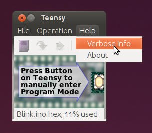
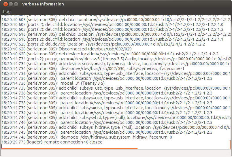
Teensy Loader has a little-known feature to show you detailed information.  Few people know of this because it’s hidden in a place nobody would look, the Help menu.

The Verbose Information window now shows events from the helper programs Teensyduino uses from Arduino, as well as the events from within Teensy Loader itself.

The events are now timestamped with millisecond resolution.  Normally this level of detailed logging isn’t needed, but when “strange” USB problems occur, a log of all the events from every software component can really help.

Teensy Loader has only a few dialog boxes.  The most important ones, alerting you to problems like the wrong board, have long been non-modal to prevent blocking event logging and responding to Arduino.  Help > About and File > Open are also non-modal, completely eliminating modal behavior.

Teensy Loader’s internal graphics handling and memory management were improved.

Miscellaneous Improvements and Fixes

USB Host support on Teensy 3.6 received small improvements.  KurtE updated the Joystick support.  A bug impacting certain hubs was also fixed.

The Serial boolean, used to check if the Arduino Serial Monitor is open, has been improved.

Teensy’s support for X-Plane flight simulator received a fix to FlightSimFloat on Teensy 3.5 and 3.6.  The Flightsim+Joystick USB type was also updated, fixing a problem where it would not be recognized by the TeensyControls X-plane plugin

A small speedup to analogWrite for DAC pins was made.

The startup delay in Teensyduino’s initialization code was reduced from 400 to 300 ms, and changes were made to begin USB enumeration sooner.  While instant startup might seem highly desirable, too-fast startup tends to cause compatibility issues with many Arduino libraries, which do not properly wait for external hardware – because all Arduino boards have slow startup.

A bug in DMAChannel.h transferSize() affecting Teensy LC was fixed.

USB Keyboard KEY_MEDIA_RANDOM_PLAY was fixed.

EthernetClient received a fix for forced connection close.

A subtle timing problem in OctoWS2811 affecting Teensy 3.5 was fixed.

When compiling on 32 bit Teensy boards, “narrowing conversion” is now treated as only a compiler warning, not an error, as has always been done on 8 bit boards.  This allows some poorly written libraries to “just work” even though their code is a bit sloppy.

Ethernet.init(cspin) is now documented in all the Ethernet examples, and on the Ethernet page.  This function is an Adafruit extension which PJRC adopted for Teensy’s version of the Ethernet library, but until now it wasn’t actually documented.

Libraries ADC, OneWire, PS2Keyboard, SerialFlash, Time, TimeAlarms (included in the Teensyduino installer) were updated.

The Macintosh version is now 64 bits software, as required by the newest High Sierra and future versions of MacOS.

Arduino Versions Supported

Support for Arduino 1.8.2 and 1.8.3 and 1.8.4 has been dropped.  The new ports menu and serial monitor are only implemented on Arduino 1.8.5.

Teensyduino is continuing to support 3 old versions of Arduino.  Arduino 1.8.1 was the last version before major changes in Arduino’s “arduino-builder” program.  Arduuino 1.6.5-r5 was the last version before “arduino-builder”, where the entire build process is controlled by the Java code in the Arduino IDE.  Arduino 1.0.6 was the last version of the very old 1.0 series.

Arduino appears to have entered a period of slower release.  Through 2016-2017, Arduino made 12 stable releases.  Since releasing 1.8.5 in September 2017, they started a 1.9 beta but haven’t made any non-beta releases.  If this trend continue, we may explore supporting specific 1.9 beta versions.

At the recent San Mateo Maker Faire, Massimo Banzi announced a developer summit.  PJRC will be participating.  My personal hope is we can move the entire Arduino ecosystem forward with contributions like EventResponder.  I plan to write more detailed articles about this effort as it develops.

Recently work was also done to support Linux 64 ARM (Aarch64), testing on nVidia Jetson TX2.  While Aarch64 support is still considered “experimental” and not part of the stable 1.42 release, if you’re interested in running on Linux 64 bit ARM, please see the last 1.42 beta for an Aarch64 build that’s essentially the same as this 1.42 release.

USB Hub Bug Hunting & Lessons Learned

This tale begins with a customer reporting this cute little 2 port USB hub wasn’t working with Teensy 3.6.
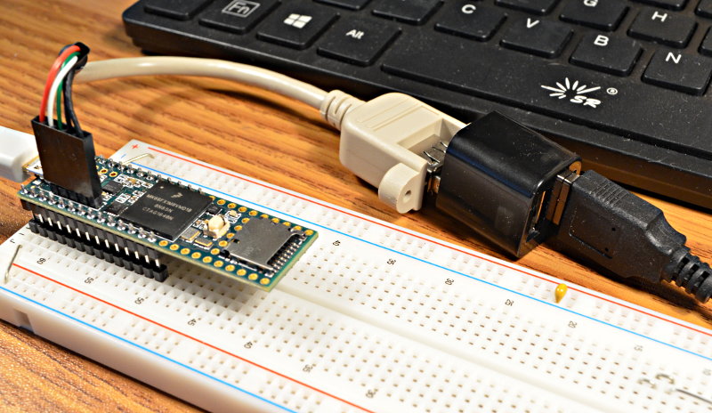
In this article I’ll show how a protocol analyzer is used, how my instincts turned out to be very wrong, and along the way dive into arcane USB details you probably won’t see explained anywhere else.

First Instincts: Fail

This article is being written from the perspective of hindsight.  You can much of the process as it actually happened on the forum thread where this problem was reported.

Most of my first troubleshooting instincts revolved around these 2 questions:

1: This hub works on Linux, Mac & Windows.  What are they doing that Teensy isn’t?

2: All other hubs work on Teensy, so what’s different about this particular hub?

I believe most people would start with these 2 questions.  In the end, both turned out to involve very wrong assumptions that were ultimately a distraction from finding the real problem.

Protocol Analyzer: Fail (Software Crash)

Usually the first step in debugging USB problems is to hook up the protocol analyzer.  I have this one, the Beagle480 from Total Phase.
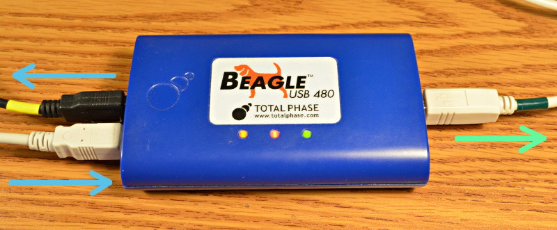
The way this works is pretty simple.  On the left side where I drew the 2 blue arrows, your USB communication passes through.  To whatever you’re monitoring, it just looks like a longer cable.  But it makes a copy of all communication happening in either direction and sends it to the port on the right (green arrow).

If you’re just making a USB device that plugs into your PC, usually you can run software to capture the data from your PC’s driver.  But when you’re making an embedded USB host like Teensy 3.6’s 2nd USB port, this is the only way to actually see what’s really happening.  The downside is the cost.  Total Phase sells this one for $1200.

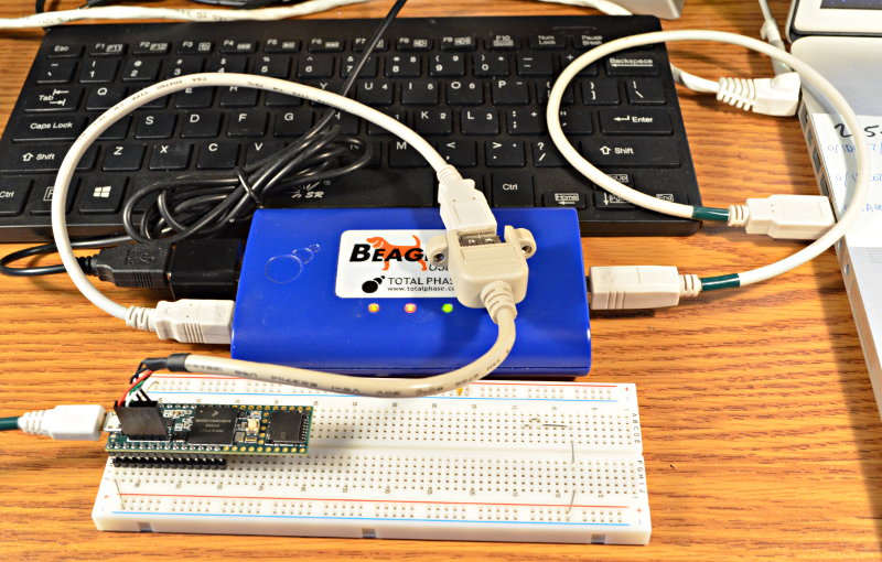
Here’s the test setup, with the Beagle480 inserted between the Teensy 3.6 and 2-port hub.  Usually quite a clutter of cables is involved, but this little hub plugs right into the side of the Beagle480.  The hub has 1 keyboard connected.  A Mac laptop is watching the USB communication, and a Linux desktop is running the Arduino IDE to upload code to Teensy.
Despite the high price, it’s not made of magic.  Inside it has a fairly small buffer memory.  It has to send a copy everything on that right side port, which can be problematic during periods of sustained fast data flow.

This case turned out to be one of those problematic situations.  Unfortunately Total Phase’s software does not handle this situation well.  The Linux version simply crashes.

The Mac version is better.  It hangs with the infamous Mac beachball.  A Force quit is needed.
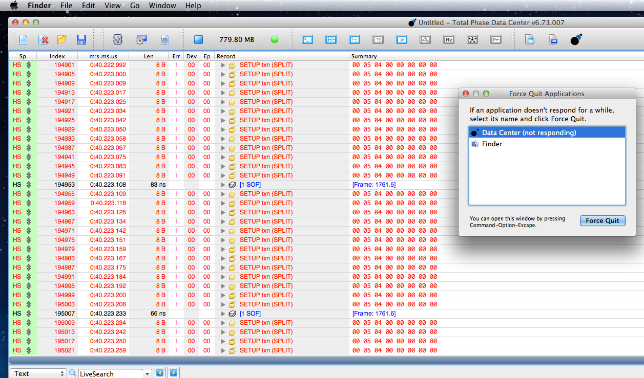
Fortunately having the software lock up means at least something can be seen on the screen, even if I could not scroll up to look at any other data.   Whatever was going wrong with this hub was causing a SETUP token to be repeatedly tried.  The timestamps show it’s happening about every 8 to 12 microseconds!

What’s Different About This Hub?

With the protocol analyzer not helping much, I decided to first focus on question #2.  All the other hubs work.  What’s different about this one?

In USBHost_t36.h on line 59 is an option to turn on lots of verbose debug printing.  But it doesn’t print much about the USB descriptors.  I decided this was a good time to fix that (rather than just plug into a PC and run a program to view), optimistically hoping the info would show some stark difference between this bad hub and all the good ones.  I spent a few hours adding this code to print descriptor info.

Here is the configuration descriptor for this 2 port hub.

Configuration Descriptor:
  09 02 29 00 01 01 00 E0 01 
    NumInterfaces = 1
    ConfigurationValue = 1
  09 04 00 00 01 09 00 01 00 
    Interface = 0
    Number of endpoints = 1
    Class/Subclass/Protocol = 9(Hub) / 0 / 1(Single-TT)
  07 05 81 03 01 00 0C 
    Endpoint = 1 IN
    Type = Interrupt
    Max Size = 1
    Polling Interval = 12
  09 04 00 01 01 09 00 02 00 
    Interface = 0
    Number of endpoints = 1
    Class/Subclass/Protocol = 9(Hub) / 0 / 2(Multi-TT)
  07 05 81 03 01 00 0C 
    Endpoint = 1 IN
    Type = Interrupt
    Max Size = 1
    Polling Interval = 12

Turns out this little 2 port hub is a Multi-TT type.  I’ll talk more about the transaction translators soon.  Most hubs have only a single TT, but 2 of my test hubs are Multi-TT.  Here’s one of their descriptors.

Configuration Descriptor:
  09 02 29 00 01 01 00 E0 32 
    NumInterfaces = 1
    ConfigurationValue = 1
  09 04 00 00 01 09 00 01 00 
    Interface = 0
    Number of endpoints = 1
    Class/Subclass/Protocol = 9(Hub) / 0 / 1(Single-TT)
  07 05 81 03 01 00 0C 
    Endpoint = 1 IN
    Type = Interrupt
    Max Size = 1
    Polling Interval = 12
  09 04 00 01 01 09 00 02 00 
    Interface = 0
    Number of endpoints = 1
 Class/Subclass/Protocol = 9(Hub) / 0 / 2(Multi-TT)
  07 05 81 03 01 00 0C 
    Endpoint = 1 IN
    Type = Interrupt
    Max Size = 1
    Polling Interval = 12

Turns out they’re an exact binary match, except for the last byte in the configuration descriptor.  I can’t emphasize enough how this process involves looking stuff up in the USB 2.0 PDF, in this case page 266.  This byte is just the hub telling the PC how much power is might draw.  The 2 port hub say 01, meaning only 2 mA which can’t be right.  But I know nothing in code on Teensy (which I wrote) ever look at this byte.  Maybe someday we’ll detect power issues, but for now it’s ignored.

Hubs also have a special descriptor for their capability.  It’s documented on page 417-418 of the USB 2.0 PDF.  Here the 3 different hubs did differ.

2 port (not working)
09 29 02 09 00 32 01 00 FF


4 port, ioGear, GUH274 (works)
09 29 04 89 00 32 64 00 FF


4 port, no-name blue color, UH-BSC4-US (works)
09 29 04 E0 00 32 64 00 FF

While I now know these differences are meaningless, and really only the 3rd byte (the number of ports) matters, at the moment I found these it seemed like this just had to explain the problem.  That 2 port hub is different.

Turns out the 4th byte describes features like which LEDs, over-current protection and other features the hub has.  The 7th byte says how long we’re supposed to wait between enabling power and accessing a port, but the bad 2-port hub says only 1 ms, much less than the other 2 working hubs.

What Would Linux Do?

With nothing apparently different between the hub, I returned to the idea that Teensy must be missing some initialization or other step that hasn’t mattered for all the other hubs, but does for this one.

It’s easy to look at what Linux does, since nothing goes wrong that crashes the Beagle480’s software.  Here’s most of the hub’s enumeration process on Linux:
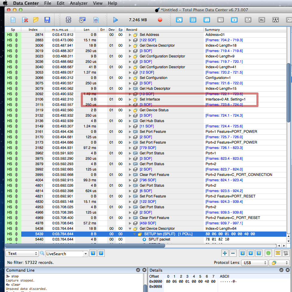
I quickly noticed Linux is sending this Set Interface control transfer.  I did testing with all 7 of the hubs I have.  This doesn’t happen on the USB 1.1 hub or the 3 that are Single-TT, but Linux does do it for all the Multi-TT hubs.

Adding this to the USBHost_t36 library took time.  The hub driver was only looking at the first 16 bytes, to see if the interface and endpoint are compatible.  I had to rewrite the hub driver to look for all the possible interfaces.  Then when it was able to detect if 2 or more exist and parse which is the best to use, I added code to actually send that Set Interface command.

It didn’t make any difference.  I’d poured a few more hours into coding, which in the long term was probably worthwhile, but still no closer to solving the problem!

Working Around Data Capture Software Lockup

I seriously considered resigning this problem to my low-priority bug list, since all the other hubs work.  I considered restructuring the enumeration code to even more closely match Linux’s approach.  I looked over the descriptor data yet again, hoping to find the answer, but no.

Clearly I needed to get around the problem with Total Phase’s software locking up.  At first I just added a “while (1) ; // die here” right before calling new_Device() to start the enumeration process after the hub detects the keyboard.  But that didn’t reveal anything useful.

I needed to let the problem happen, but then shut off the USB port before the Beagle480’s buffer could overfill (or whatever other problem causes the Total Phase software to lock up).  Ultimately I did this:

    if (state == PORT_RECOVERY) {
        port_doing_reset = 0;
        print("PORT_RECOVERY, port=", port);
        println(", addr=", device->address);
static IntervalTimer stoptimer;
stoptimer.begin(panic, 1000);
        // begin enumeration process
        uint8_t speed = port_doing_reset_speed;
        devicelist[port-1] = new_Device(speed, device->address, port);

When I put in terrible debug code, I like to give it very odd indenting so I’ll see it when/if I later forget to remove it!  In this case, a hardware timer is started to generate an interrupt in 1 millisecond, which calls panic().

The panic() function looked like this:

void panic()
{
    GPIOE_PCOR = (1<<6); // turn off USB host power
    Serial.printf("Panic stop\n");
    while (1) ;
}

With this I was finally able to see the beginning of the problem.
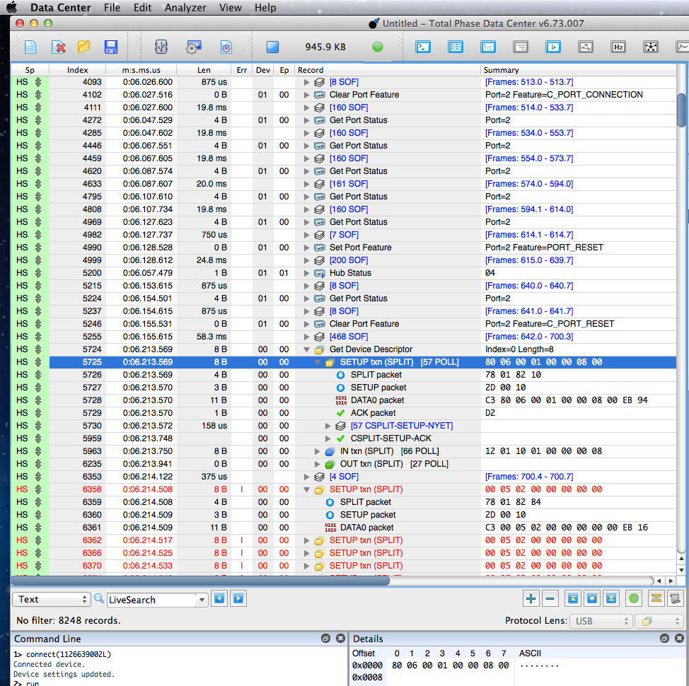
Somehow the bad 2 port hub was indeed working, at least for the first control transfer which reads 8 bytes of the device descriptor.  But then everything goes wrong and nothing works.  The host controller keeps trying to resend the Set Address command… at least for 1 millisecond, until the panic() function abruptly shuts off the USB port’s power.

Realizing What’s Really Wrong

I wish I could tell you there’s a reliable process to go from actually being able to observe the problem to understanding it.  There isn’t!

In this case I spent several hours re-reading the USB 2.0 spec, staring at that screenful of info, and basically just guessing.  For a while I considered there might be some sort of electrical interference problem unique to this hub, somehow triggered by completing that first transfer.

It literally took hours to focus on this 1 byte which turned out to be the cause of so much trouble.
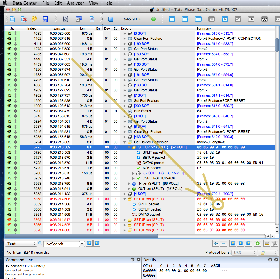
To understand this byte, you need to know about USB split transactions, which are probably among the most arcane of USB features.  This next part will be quite technical, so perhaps skip to the end if you’re not in the mood for intensely low-level USB protocol details.

Split transfers are used only between USB hosts and hubs.  If you’re making a USB device, you’ll never see this type of USB communication.  They’re used only when a host at 480 Mbit speed needs to communicate with devices at 12 or 1.5 Mbit.

When USB 3.x is used, all the 5+ Gbps communication happens on dedicated wires.  The cables & hubs have a redundant 480 Mbit path. When you use a 12 or 1.5 Mbit device on a USB 3.0 hub, that slow communicate is done using split transactions on the 480 Mbit line.  Slow speeds are never translated to the 5 Gbps lines.

USB has a lot of very specific terminology.  From smallest to largest, communication is in Tokens, then Transactions, then Transfers.  I’m not going into details here, other than it’s important to remember we’re dealing with 3 starts-with-T junks of data.  Tokens are the smallest.  Transactions are bigger, made up of Tokens.  Transfers are the largest, maybe of of Transactions & Tokens.

These SPLIT tokens communicate with a Transaction Translator (TT) inside the hub.  When the host wants to send a transaction at 12 or 1.5 Mbit, it sends a SPLIT-START token to the hub’s TT.  If the TT isn’t busy, it acknowledges and begins working on the slow communication.  That sequence of tokens is a transaction, also called split start (maybe confusing if you don’t know the context).  Later the host sends SPLIT-COMPLETE.  If the TT has finished, it replies with ACK, and if it’s still busy it replies with NYET.

Here’s the diagram from the USB 2.0 spec on page 202 showing this for OUT transactions.  Sadly there isn’t a diagram specifically for SETUP transactions, but my guess is this should be pretty close.  Did I mention this sort of work is all about guesswork and re-reading technical specs over and over?
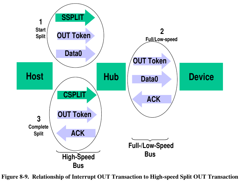
Total Phase’s software is very nice.  It normally shows you one Transfer per line.  If you want to see the Transactions that made up that transfer, you click the little triangle to expand.  Likewise if you want to drill down to see the actual tokens, you can.  Here’s the first successful transfer.  Hopefully you can see this more-or-less corresponds to Figure 8-9, except SETUP instead of OUT.  Of course, we only see the stuff from circles #1 & #3 since we’re connected between Teensy and the hub.

In this case, we can see Teensy sent 58 SPLIT-COMPLETE tokens while the hub slowly send that SETUP token at 1.5 Mbit to the keyboard, where the hub replied with NYET to the first 57, then finally an ACK.

This is important, because the process of figuring out why something isn’t working almost always involves first looking at the deeper details of what it’s supposed to do when it does work.

With that in mind, here’s an expanded view of the first Set Address transfer that fails.

Remember the software is showing us nesting of Tokens inside Transactions inside Transfers.  So the 3rd line is actually the first real data.  This badness begins with the bytes 78 01 82 B4.

Earlier 78 01 82 10 was considered ok.  But 78 01 82 B4.  So what does that last byte mean?  Again the answer is digging into the nitty gritty details in the USB 2.0 document.  It happens to be on the same page as that diagram above.
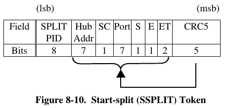
Even though going from 10 to B4 looks like a big change, in fact the top 5 bits are a CRC check which is expected to be totally different if any of the checked bits changed.  So really this means just one of the “ET” bits flipped from a 0 to 1.

The meaning of those ET bits is documented a few pages later.
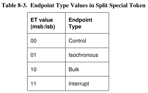
These bits were 00 for Control, but somehow became 10 for Bulk.  That’s definitely not right!  We’re sending a SETUP token, and that token has the endpoint number encoded within (also documented elsewhere in chapter 8….)

Where This 1 Bit Went So Wrong

The good news is this last part, going from an understanding of what’s wrong to finding the mistake causing it, is relatively easy.  It took only about an hour.  While I didn’t know exactly what controlled those ET bits, I was pretty sure it was something in the EHCI controller’s QH or qTD data structures.

USB controllers implementing EHCI are very unlike traditional embedded peripherals, where a handful of fixed register addresses control everything.  EHCI gets almost everything from main system RAM, where it’s regularly using DMA to read linked lists and binary tree data structures to find out what work you want it to perform.

For each pipe/endpoint each USB device, you create a QH structure (except complexities for isochronous… but trying to keep this simple).  Here’s the EHCI diagram for the QH structure.
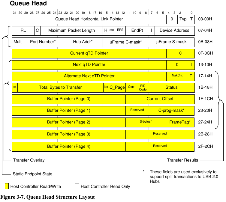
The first field is used for the linked lists or inverted tree pointers.  The next two are where you actually configure how the hardware will communicate.  The big yellow area is written by the hardware, coping other info there temporarily as it works on the Transfers you want.  (Yes, the hardware deals in Transfers and automatically does the Transactions & Tokens)

While there’s a lot of small fields in those 64 bits, the “C” bit turned out to be the key.  The EHCI spec documents it as:

Control Endpoint Flag (C). If the QH.EPS field indicates the endpoint is not a high-speed device, and the endpoint is an control endpoint, then software must set this bit to a one. Otherwise it should always set this bit to a zero.

Fortunately the code uses C structs to with distinctive names to represent the QH and other EHCI data structures.  A quick grep of all the code turned up everything that accesses this field.  Only a few of them actually write to it.

Ultimately the bug turned out to be just this 1 line function called pipe_set_maxlen()

pipe->qh.capabilities[0] = (pipe->qh.capabilities[0] & 0x8000FFFF) | (maxlen << 16);

Of course if you look at the 2nd line in the QH documentation, this is incorrectly zeroing too many bits, destroying the C bit and part of the RL field.  It should be:

pipe->qh.capabilities[0] = (pipe->qh.capabilities[0] & 0xF800FFFF) | (maxlen << 16);

Indeed applying this fix made the “bad” 2-port hub work quite nicely.

Headslap Moment

After I found the fix, I looked one last time at the question “All other hubs work on Teensy, so what’s different about this particular hub?”

Here’s the communication with that keyboard through one of the “good” hubs!
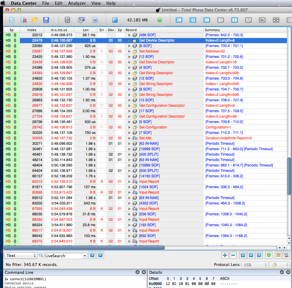
Turns out the code has been sending improper SPLIT-START tokens all along, but every hub I own and the numerous hubs other people have used all were able to work anyway!  The different was this particular hub was actually rejecting the bad tokens.

In all this time, developing this library earlier this year and all this recent work to track down this bug, apparently I never actually connected the protocol analyzer and watched the “good” hubs really communicating with low speed devices!  Could have saved a *lot* of work.  Now I know, in hindsight.
Twitter Taxi

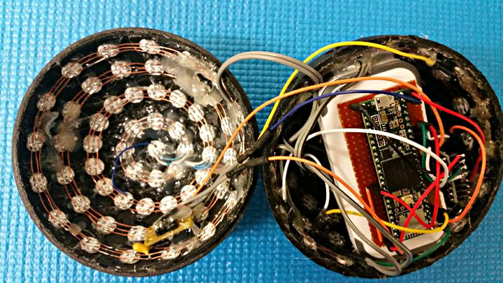
Forum User digital11 outfitted a 1922 Checker Cab with Ws2811 LEDs that react to music that can be requested over Twitter.

Check out this video showing the LEDs in dancing action.

Some of the technical details ditigall11 provided on this project include:

5 Teensy’s running OctoWS2811 (Probably went a little overboard here, as I wanted the Teensy’s as close to the strips as possible, so I’m not using OctoWS2811 to its fullest, but I’m sure PJRC doesn’t mind :P)

Ableton Live/Max4Live/Jitter handling the music playing & video generation. Wrote a serial external for Max that basically generates a bytestream formatted for OctoWS2811 from a jit.matrix, so any video can be piped in realtime to the Teensy’s, with whatever fx/beat syncing is desired (Major props to nlecaude for the foundational work on this.)

Custom OSX app to monitor Twitter, queue up the requested songs, and update a tv display showing the song queue, available songs, and currently playing song.


Why APA102 LEDs Have Trouble At 24 MHz

It’s well known long APA102 LEDs strips have have trouble at 24 MHz, usually after 150 to 250 LEDs.  But why?  Here’s my attempt to investigate.

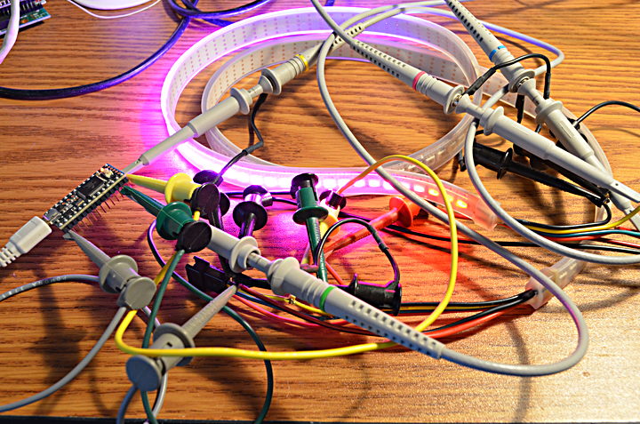
One tempting explanation is signal quality problems due to horribly messy unterminated wiring carrying high speed signals, as in this photo!  But it turned out to be a more fundamental timing problem.

In this test, a Teensy 3.2 runs the FastLED “Cylon” example with this line:

 LEDS.addLeds<APA102,11,13,RGB,DATA_RATE_MHZ(24)>(leds,NUM_LEDS);

NUM_LEDs was set to 160, and I connected a strip of 144.  The oscilloscope traces are the signals which arrive at the end of the 144 LED strip.

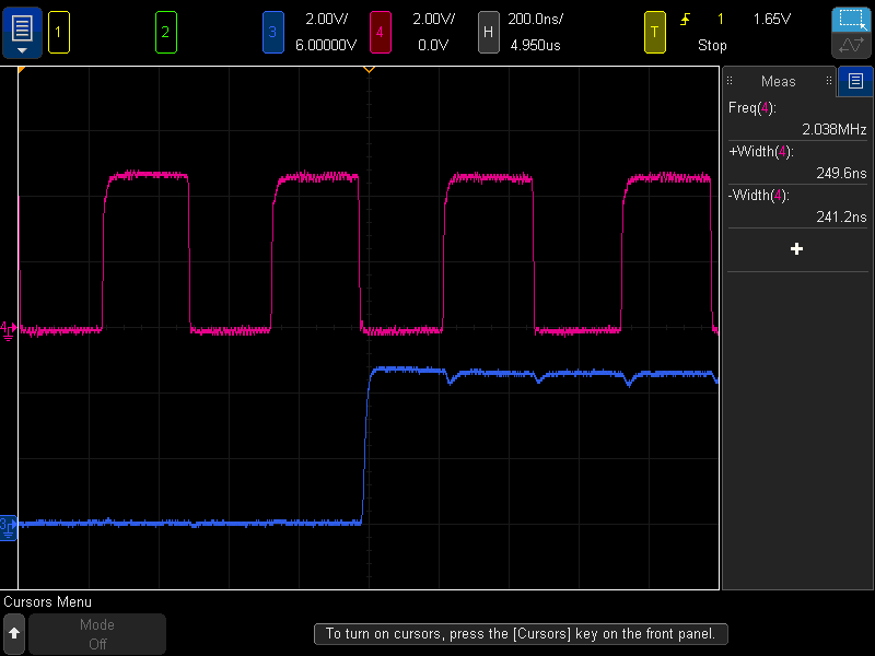
First, I set the clock speed to only 2 MHz to see the “normal” waveforms output by the last APA102 LED.

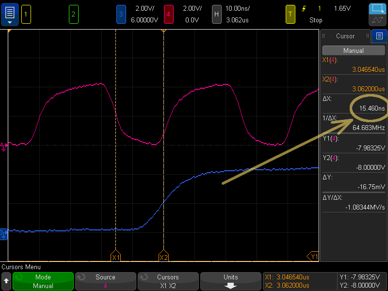
The main thing to observe here is the APA102 output changes its data line (blue) at the falling edge of the clock (red).  You might notice a slight delay from the falling edge of the clock to the change in data, but it’s tiny relative to the slow 2 MHz clock cycle.

At 24 MHz, the delay is much more significant.  In this case I measured approximately 15 ns delay from clock to the data changing.

You might also notice the red trace doesn’t look like the 50% duty cycle SPI clock signal.  I believe this, together with the data delay, is the main cause of APA102 issues on long LED strips.

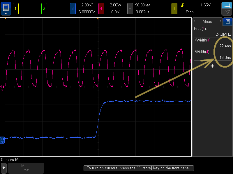
Here’s another measurement of the clock.

Each APA102 LED is supposed to regenerate the clock signal.  Ideally this is supposed to allow a very long LED strip.  But it appears each APA102 lengthens the clock high time and shortens the clock low time slightly.  This might be internal to the APA102 control chip, or it could be simply due to the clock output driver having a faster fall time than rise time, causing the following APA102 to receive a slightly different clock high time.  Perhaps the APA102 controller chip has a better N-channel transistor for pulling the clock output low than the P-channel transistor for driving it high?

After 144 LEDs, the clock low time on this strip has shrunk from 20.83 ns to approximately 18 ns.

With the data output delayed 15 ns after the falling edge, this leaves only 3 ns before the next APA102 LED captures the data on the rising edge of the clock.  As the strip gets longer, each APA102 reduces the clock low time, until it’s shorter than the clock to data delay.

FastLED defaults to 12 MHz SPI clock for APA102 LEDs on Teensy 3.x, which should allow for several hundred LEDs before this clock duty cycle change becomes a problem.

This test was just one APA102 strip I purchased about a year ago.  The Chinese semiconductor manufacturers making these LEDs have a history of changing the silicon without any notice.  I also only tested at room temperature, using only 1 example program which doesn’t drive the LEDs anywhere near 100% duty cycle (more heating).  I powered the 144 LEDs with 5V from both ends, but didn’t make any measurements of the voltage near the middle of the strip.  Power supply voltage might matter.  In other words, your mileage may vary.

But hopefully this helps with understanding what’s really going on, why short APA102 LED strips work so well with the fast clock speeds, but fail when using very long strips, even though the LEDs are supposed to regenerate the clock and data as they pass it down the strip.

Fast pulse counting with interrupts and why nested priority really helps

A question was recently asked on the forum, how fast can attachInterrupt count pulses.  I did some testing to find out, and made this video.

Turns out Teensy 3.2 can run about 1.25 million interrupts per second.  Teensy 3.6 can do about 2.55 million per second.  But these depend on assigning a top priority to the interrupt, as explained in the video.

Of course, both boards can use a timer to count pulses at very high rates, at least 30 MHz.

How Much Current Do WS2812 / NeoPixel LEDs Really Use?

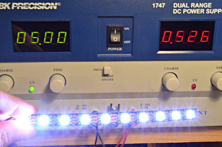
Today this question came up on the FastLED Google+ Group, so I decided to actually measure.  Turns out, I was surprised to learn it varies quite a lot, depending on which type you actually have.

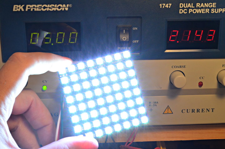
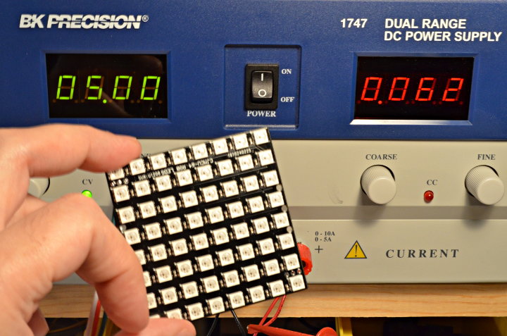
Type A – Approx 33.5 mA Maximum

My first test was this little board with 64 LEDs.

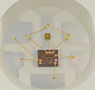
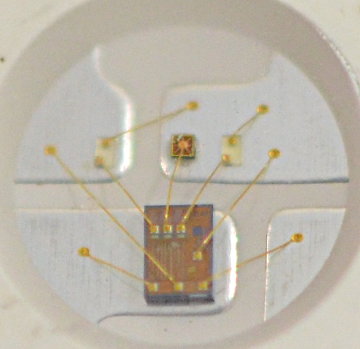
This is much lower than the 50 to 60 mA per LED budget that’s often mentioned.  Here is a macro shot of the actual chip in these LEDs:

Type B – Approx 52.5 mA Maximum

Since the first test turned out so low, I also dug up a small strip of WS2812 LEDs from a project made a couple years ago.

These actually are just above the “normal” 50 mA budget.  They also have a distinctly different chip inside.

Both of these were called “WS2812B”, but obviously they are quite different.

Both Types – Approx 1 mA When “Off”

One thing that is nearly identical to both types is the current used by the controller chip when the LED is “off”.

Both are just under 1 mA per LED when just sitting there dark.

This was just a quick test with two WS2812B LED products I had on hand.  There may be even more types.  But at the very least, hopefully this can give you an idea of how much power you might need for a LED project, depending on which type you actually have.

Non-Blocking WS2812 LED Library

Last weekend I wrote a new WS2812 LED library featuring non-blocking performance.

A common problem with WS2812 / NeoPixel LEDs is creating their control signal with precise timing conflicts with other timing-sensitive software.  Adafruit NeoPixel completely blocks all interrupts.  FastLED can be configured to allow other interrupts, but any other library using interrupts for more than several microseconds can disrupt the WS2812 signal.

OctoWS2811 has offered non-blocking performance on Teensy 3.x since early 2013.  But it consumes 8 pins and places restrictions on 1 or 2 others, which makes it difficult to use in many projects needing some of those pins.  OctoWS2811 is designed for large LED projects (500 to 6000 LEDs), which is “overkill” for many projects using only dozes or even a few hundred LEDs.

Especially for projects using NeoPixel products with the Teensy Audio Library, or trying to receiving incoming serial data (especially DMX lighting control), we have long needed a simple, single-pin, easy-to-use library that doesn’t interfere with interrupts.  For a long time I’ve meant to write this library, and this recent forum conversaton finally gave me the push to get it working to truly solve the NeoPixels+Audio isssue!

Inverted Serial Transmit

WS2812Serial uses one of the hardware serial ports to actually transmit the Ws2812 data.  This idea certainly isn’t new.  This message is the oldest reference I could find of the basic idea.

The serial port is configured to run at 4 Mbit/sec, which is exactly 5 times the 800 kbit/sec speed WS2812 LEDs expect.  Every 5 data bits becomes one cycle of the WS2812 signal.

Standard 8N1 format serial sends 1 start bit, 8 data bits in least-significant-bit-first order, and then 1 stop bit.  In this case, the signal is inverted from the usual TTL level output.  Teensy LC & 3.x have hardware built in to invert the signal.

Since the start bit is always high, to send a zero bit to WS2812 the first 4 data bits are configured low.  To send a one bit, the first 3 are configured high and the 4th low.  The other half of the byte becomes the next WS2812 bit.  Bit 4 must always be high, and bits 5 to 7 control the data seen by WS2812.  The stop bit is always low, which automatically completes the 2nd WS2812 data.

Originally I tried using only 3 bits per WS2812 time slot, with 2.4 Mbit/sec serial baud rate.  Many of the WS2812 datasheets say the timing allows up to 450 ns pulse width, so in theory this 417 ns pulse should work.  In practice it did work with some WS2812 LEDs, but not others.  In the end, I changed to 4 Mbit/sec which allows it to work with all WS2812 / NeoPixel LEDs.

Direct Memory Access (DMA)

To achieve non-blocking performance, and to run efficiently at 4 Mbit/sec baud rate, DMA is used to copy the data directly from memory to the serial port.

The result is a perfectly continuous WS2812 output which does not require any interrupts and leaves the processor free to run other libraries or your program to compute the next frame of LED data.

The need to compute all of the serial data before each update does lead to the one major drawback of this non-blocking approach: memory usage.  Normally with FastLED or Adafruit NeoPixel, only 3 bytes of memory are used per LED.  WS2812Serial requires 15 bytes, the normal 3 for drawing, and 12 for composing the serial data.

Fortunately the code is fairly simple.  Here is the entire show() function which updates the LEDs.  In the middle you can see “x = 0x08” which sets the begin bit for the 2nd half of each byte’s WS2812 output, and then the two logical OR operations which control the groups of 3 bits which are the shaded portion of the drawing above.

In this code sample you can also see my DMAChannel.h abstraction layer for DMA transfers.  It is my attempt to make DMA simple to use, like other Arduino libraries.  Obviously things are not quite there yet, especially for Teensy LC where you can see I had to resort to directly programming the DMA controller registers, rather than using the functions to configure the source, destination, transfer size and count.

At some point I intend to write a detailed article about how DMA works.  Mike from Hackaday has been asking me to do this for years!  If you’d also like to see it, remind me too….

One other possible idea for this library might involve using two DMA channels and their interrupts, to allow a smaller serial buffer.  The basic idea would involve rendering only part of the output, and configuring each DMA channel to send half.  Each each completes and generates an interrupt, another chunk of the output could be generated and the just-finished DMA channel could be quickly reconfigured to send the next chunk.  Ideally, this could allow a relatively small memory buffer.  It would require interrupts, but if they are delayed by other libraries or code, hopefully a user could make a trade-off between memory usage and allowable interrupt latency.

For now, WS2812Serial simply requires a big frame buffer and gives completely non-blocking performance.  No interrupts are ever used.  That does consume extra RAM, but the huge benefit is compatibility with other code or libraries require interrupts or CPU time while the LEDs update.

Pilot Light Flame Sensor for Burning Man Art

I recently built flame sensing electronics for Martin “Moltensteelman” Montesano’s “Three Wishes” art project to be shown at Burning Man.

As a safety precaution, certain types of fire art installations are required to use sensors on their pilot lights.  If wind blows out the pilot, the gas must automatically turn off and other valves controlling high pressure propane directed at that pilot must be prevented from opening.

In this article, I’d like to share with you details of how I built a circuit board for Martin’s project to meet these requirements.

Safety First  Disclaimer First

This Information (web page and related hardware and software files) are provided “as is” and without warranty of any kind, expressed or implied, including but not limited to the implied warranties of merchantability and fitness for a particular purpose.  In no event shall PJRC.COM, LLC or Paul Stoffregen be liable for any direct, indirect, incidental, special, exemplary, or consequential damages arising in any way out of the use of this Information, even if advised of the possibility of such damage.

My hope is you’ll find this article interesting.  If you do make use of it, remember it’s something you found for free on the Internet.  Ultimately it’s your responsibility to manage and accept responsibility for the risks of any project you build.

How To Sense A Flame

There are at least 3 ways to sense fire.

  1. Infrared Light: If you search for flame sensors and Arduino, nearly all tutorials and inexpensive products use a simple IR diode or photo-transistor circuit.  Infrared light also comes from many other natural and man-made sources, making this approach very difficult to implement reliably.  The absolute last thing you want in this application is a false reading allowing high pressure propane to flow!
  2. Heat / Temperature: Thermocouples and Thermopiles are commonly used in water heaters and gas fireplaces.  However, temperature sensing can be quite a challenge for an outdoor application exposed to wind and made with metals that can remain hot for quite some time.
  3. Conductivity / Flame Rectification: Modern gas furnaces use this highly reliable technique.  Gas flames are conductive and act as a rectifier, similar to a diode.  The rectification effect is supposed to be due to a difference in the mobility of the positive ionized particles (burning fuel) and free electrons.  Applying a voltage to the flame can move the electrons much moreso than the positively charged ions.  The best explanation I’ve found is in this paper by Andreas Möllberg.

Martin had already purchased this flame sensor rod (Rheem 62-23543-01), based on the fact that it’s the sensor used in a common furnace, that it has a convenient L-shape which works nicely for his art’s pilot light design, and that it’s only $7.  So the path of flame rectification sensing was chosen…

He also rigged up 1 of the Three Wishes pilot lights to a regulator and fitting so I could run in in by back yard from my barbeque’s propane tank!

With this sensor and test gear, I started on electronics to make it actually work.

Flame Rectification Circuitry

I must confess, before this project I had never even heard of flame rectification.  Reading Möllberg’s paper, it was clear the flame acts like a diode with a very high value resistor in series.  Many guides exist for training furnace technicians with good info.  So the basic idea is to apply a substantial AC voltage to the flame and then look for a tiny pulsed DC current.

After a couple false starts, a little more searching turned up several patents.  I tried a couple of these, ultimately settling on US5439374, partly because it allows an actual analog reading (many circuits are just flame vs no-flame indicators), and partly because it expired in 2013.

US5439374’s basic idea is current can only take 2 paths to get to the flame, either through capacitor #24, or through the resistors and transistor.  Since capacitors can only pass AC current, if any net DC current flows through the flame, it must also flow through the transistor’s base-emitter junction.

An amplified copy of the DC current flows through the transistor and diode, causing capacitor #50 to charge up.  Higher DC flame conduction causes this capacitor to charge up faster.

I built an adaptation of the US5439374 circuit on a breadboard.

Much of this circuitry generates the AC voltage, because it’s meant to run on 12 volts DC.  From left to right, a Teensy LC creates a AC waveform using its DAC output.  It goes through a low-pass filter to smooth the stairstep edges, and an amplifier with gain of 3 to turn it into a 10 volt peak-to-peak waveform.  The amplifier uses a pair of transistors to buffer its output, which then drives a small transformer with approximately an 1:11 ratio.  The result is about 40 volts AC (rms), or about 112 volts peak-to-peak.  Rather than use 50 or 60 Hz as in a furnace, the Teensy generates 1kHz AC, which allows for faster sensing and a smaller transformer and capacitors.

The parts in the upper right area of the breadboard are the US5439374 circuit.  I used a 2N5087 transistor and after some fiddling settled 1nF & 10nF capacitors.  On the far right side are 15M, 10M, 10M resistors and a diode meant to simulate the flame.  As you can image, I tried many combinations of these, and in this photo a wire is testing what happens when the output shorts to ground.  It turns out the US5439374 circuit works extremely well, able to measure diode plus 35M ohm resistance quite well.

I added one more NPN transistor across the capacitor, which you can see just to the bottom right of the transformer.  The other half of the dual opamp chip turns on this transistor if the capacitor’s voltage rises above 3.3V.  It turns out this circuit can gradually charge the capacitor to about 20 volts, so this protects the Teensy’s analog input pin, in case the code isn’t running and regularly discharging the capacitor before it can accumulate too much voltage.

First Test With Fire

No amount of testing with resistors and diodes could really satisfy my lingering doubt.  Would this would really work with actual fire?  So it was time to run a first test with the breadboard circuit connected to a real flame.

Martin came over and we ran it for the first time with real fire.  The Teensy had just a simple program measuring the elapsed microseconds for the capacitor to charge to 2 volts.

I’m happy to say the flame gave a really strong signal.  I had done a lot of testing with 10M to 35M resistors.  Even with the gas turned down very low, with the flame just barely flickering, we got readings (low numbers) printing in the serial monitor.

With the circuit working, it was time to turn it into a usable design to control the pilot light and other valves.

Circuit Board

I quickly designed a circuit board with the flame sensing circuit, a power mosfet for controlling the pilot light gas valve, a relay to enable the other valves, a special timer circuit I’ll describe in more detail in the next section, and all the usual power input conditioning you’d expect.

Since time was running short, I ordered boards from Sunstone Circuits.  They have a very rapid service.  The quick turn prices are better if you choose the option for no solder mask or silk screen.  I put the order in for these boards on Wednesday for a 2-day turn.  Sunstone shipped 1 day early, so I actually got these on Friday!  Thanks Sunstone.  🙂

This was the first board I built.  As you can see, it has a smaller transformer.  I only had 4 of the larger, better transformers, so I wanted to try this one first.

Luckily, the board worked.  No major mistakes.  However, during testing I did discover one small oversight.  The B130 clamping diode has a small leakage current.  It’s nowhere near enough to turn on a solenoid, but it does make the output measure about 10 volts with a multimeter (having about 10M input impedance).  On the final boards I added a 4.7K resistor, so the output is nearly zero volts when off.  The rest of the info in this section has this extra 4.7K resistor added.

Circuit Board Parts:

  1  Teensy LC
  3  LED, Green
  1  LED, Red
  1  Relay, RT424012, Mouser 655-RT424012
  1  Terminal Block Header, 4 pin, Phoenix 1755752, 277-1152-ND
  1  Terminal Block Header, 6 pin, Phoenix 1755778, 277-1154-ND
  1  Connector, 2 pin right angle header, Molex 22-05-3021
  1  LMC6482A Opamp, LMC6482AIMX
  1  74VHC123 Dual One-shot, 74VHC123AMXCT-ND
  1  LM2940IMPX-5.0 Voltage Regulator, LM2940IMPX-5.0/NOPBCT-ND
  1  Transformer, Audio 1K:8ohm, Mouser/Xicon TU003, Mouser 42TU003-RC
  2  IRFR5305 Mosfet, P-channel, IRFR5305PBFCT-ND
  2  PNP Transistor, 2N5087, TO-92, 2N5087-ND, 2N5087CS-ND
  2  Resistor, 10 ohm, 1%, 0805
  3  Resistor, 220 ohm, 1%, 0603
  2  Resistor, 470 ohm, 1%, 0603
  6  Resistor, 1K, 1%, 0603
  1  Resistor, 4.7K, 1%, 0805 (add between gas solenoid output pins)
  8  Resistor, 10K, 1%, 0603
  1  Resistor, 22K, 1%, 0603
  2  Resistor, 47K, 1%, 0603
  1  Resistor, 100K, 1%, 0603
  2  Resistor, 220K, 1%, 0805
  1  Resistor, 470K, 1%, 0805
  5  Resistor, 1M, 1%, 0805
  3  Capacitor, 4.7nF, C0G, 0805, 1276-6729-1-ND
  1  Capacitor, 1nF, 100V, Polyester Film, 493-3476-ND
  1  Capacitor, 10nF, 50V, Polyester Film, 493-3455-ND
  2  Capacitor, 0.1uF, 50V, X7R, 0603
  7  Capacitor, 1uF, 35V, X7R, 0805
  1  Capacitor, 100uF, radial, 6.3mm diameter, 493-13394-ND
  1  Capacitor, 100uF, 6.3V Tantalum
  1  Capacitor, 470uF, axial, 4053PHCT-ND or 4054PHBK-ND
  3  Diode, Dual Common Cathode, MMBD4148, MMBD4148CCCT-ND, MMBD4148CC-TPMSCT-ND
  1  Diode, Dual Schottky Common Cathode, BAT54C, BAT54C-FDICT-ND
  1  Diode, Schottky, 1A, 30V, B130, B130-FDICT-ND
  1  Diode, Zener, 12V, 1SMB5927, 1SMB5927BT3GOSCT-ND
  4  NPN Transistor, MMBT3904, MMBT3904FSCT-ND
  1  PNP Transistor, MMBT3906, MMBT3906FSCT-ND
  1  Pushbutton, 401-1426-1-ND (optional)
  2  header, 14 pins
  1  header, 4 pins (ok to cut from longer header)
  2  socket, 14 pins
  1  socket, 4 pins (ok to cut from longer socket, may need to shave side to fit)
  0  Connector, 3 pin right angle header, Molex 22-05-3031 --- not used
  0  MAX3483 RS485 Transceiver --- not used

If you’d like to get some of these boards made, I’ve shared the design on OSH Park.

Here is the parts placement diagram for building the board.

When bringing up this board for the first time, there’s quite a lot of hardware to test.  First, I applied 12V power without a Teensy installed, only to check the 5V power.  If something is wrong with the power input, discovering it early can save the Teensy and most of the other circuitry.

I created this hardware test sketch to help verify most of the board’s hardware.  While running, the gas solenoid output turns on for 1/2 second and then off for 1 second.  It’s best to check the timing with a logic analyzer or oscilloscope, but if the timer circuity isn’t working the likely failures are no changes or 3 rapid pulses every 1.5 seconds.

Holding the pushbutton changes the output to the relay, to allow testing the other timer, the relay & its transistor, and of course the pushbutton.

The test program also generates a 1.2 volt AC waveform (3.3 volts peak-to-peak) at Teensy LC’s DAC pin.  The opamp circuitry is supposed to increase it to 3.6 volts AC (10.3 volts peak-to-peak) at the transformer input.  The transformer should step it up to approximately 40 volts AC (112 volts peak-to-peak on an oscilloscope).  When testing these voltages, oscilloscope probes should be in 10X mode.

The final test to check the US5439374 flame sensor circuit was done with the board programmed with the final code.  It prints the flame measurement to the Arduino Serial Monitor.  Testing is pretty easy to do with resistors and diodes.  A fast non-Schottky diode is best.  I used a UF1003-T diode.  Smaller numbers are stronger signal levels.  The circuit should be able to measure at least 25M in series with the diode, but without the diode it should see no signal (highest number printed).

Building and testing these boards took most of a weekend.  Here’s the final 4 boards.

Safety Features

The primary safety feature in Martin’s project is use of normally closed solenoid valves and plumbing rated for high pressure propane.  All failure modes need to avoid keeping power applied to the solenoid valves.  When the valves are off, the propane is contained.

Rather than allowing the Teensy pins to directly control voltage to the valves, I added hardware timers using a 74VHC123 chip.  This part works essentially the same way as the familiar 555 timer chip, with voltage comparators and set-reset latches.  But unlike the 555, it is designed to be retriggerable and it has logic for true edge triggering.  These can be added to a 555 with extra parts, but each adds design compromises.  The 74VHC123 gives both features in a highly reliable chip.

The timer turns on its output when it sees the rising edge of a trigger pulse.  The edge trigger is important.  Microcontroller failure modes tend to result in the pins stuck in one state.  The timer does not respond to its input stuck high or low.  Only the low-to-high transition begins the timing cycle.

This oscilloscope screenshot shows the waveforms when running the hardware test program.  The timer keeps it output high for 0.25 seconds following any rising edge trigger.  The test gives 3 pulses, then waits.  The waveform after this 3rd pulse tests a failure where Teensy might crash or lock up or otherwise fail.  The hardware timer automatically turns off the propane solenoid valve after 0.25 seconds without another pulse.

The code Teensy runs also implements extra safety features.  The main one is a count of good flame readings.  Pulses are only sent to the timer if the previous 4 sensor readings all show a flame signal.  While the US5439374 circuit works very reliably, this extra check is meant to have the gas turn off in the case where only intermittent measurements are made.  Only when a consistent pattern of good flame readings are seen can the timers be triggered to turn on the outputs.

The code also measures the time while the manual start button is pressed.  If this button were to fail (in the pressed state), and the pilot light is out, we don’t want to turn on any gas.  A 20 second time limit is used, and it’s initialized to 100 seconds at startup.  The manual start only works if the button is first observed as not pressed, to reset this time limit, and then can only keep the gas turned on for 20 seconds.  If some unexpected mechanical failure results in an object falling onto the button, the worst case scenario is 20 seconds of pilot light gas.

Dust Resistant Construction

Anyone who’s been to Burning Man knows of the extreme dust.  So I started the enclosure design around this IP67 rated pushbutton, which has real threads & a nut (so many are the flimsy press-in type).

This button photo is from the Digikey page, and really, I’m a bit curious how they manage to get such a perfect photos with the parts all standing?  Must be tricks real photographers know…

With the project coming together on a tight timeframe, I laser cut the enclosure from acrylic sheets I had on hand.  Here is the lid made from thin material, due to the depth of the button’s threads.

Some time ago, I purchased samples of rubber material to someday try to make gaskets for a waterproof box.  This was the day…

Again, a real photographer could have probably captured this without so much blur.  Maybe I could have with a tripod?  Maybe not?  The camera has a lot of trouble focusing on a black sheet.

Here is a first fit check of the gasket against an early attempt at the base.

One of the many little lessons I learned is the squeezed rubber exerts force against the plastic, enough to make it bend with this thin piece.  I ended up discarding this part and cutting bases from the thicker material to (hopefully) avoid gaps from the base bending.

The gasket seals the lid against the base, and the PCB against the base where the 2 connectors fit.  For the lids, I just glued pieces together with normal acrylic cement and then used silicone caulking compound along the inside seams.

Here are the 4 completed lids with the buttons installed, and the final thicker base, ready to be assembled.

I’d like to remember this part of the project going smoothly, but the truth is I ended up making a few different base designs.  Silly mistakes.  Here’s the final fit check.

One other imporant piece was the height of these standoffs.  The side walls are made to be about 0.015 inch taller than the combined standoff+PCB height, so there’s a slight squeeze applied to the rubber gasket.

Here’s the final assembly with the screws.  It stands off the table slightly, since the connectors protrude from the bottom.  Maybe not the most conventional design, but this was done pretty quickly.

One thing I considered but didn’t do was buy special sealing machine screws.  Hopefully the ordinary screws will work.  I guess we’ll soon know if this design resists the Playa dust of Burning Man, though Martin will probably also end up installing these inside a box that offers another layer of protection.

Here is a list of all the materials I used to make these enclosures.

  1  Terminal Block, 4 pin, Phoenix 1757035, 277-1013-ND
  1  Terminal Block, 6 pin, Phoenix 1757051, 277-1015-ND
  1  Pushbutton, IP67 waterproof/dustproof, GPB556A05BR, CW158-ND
  1  Connector housing, Molex 22-01-3027, WM2000-ND
  2  Connector crimp contact, Molex 08-50-0114, WM1114-ND
  5  Laser cut acrylic, 0.212 thick
  1  Laser cut acrylic, 0.100 thick
  1  Laser cut rubber, 0.063 thick
  4  Hex standoff, 4-40 thread, nylon, 36-1902D-ND
  4  Machine screw, 4-40, 1/4 inch
  4  Machine screw, 4-40, 1/2 inch
  2  #26 wire
  2  printed label, attach to Terminal Blocks

The laser cut design was create with Corel Draw v6.  You can find the file flame_sensor.cdr in this Github repository for the code.  These were cut with an Epilog laser, which has a driver that ignores the thicker lines when only vector cutting.

One final addition was printing these labels for the connectors.  Troubleshooting electronics in the desert can be frustrating.  Hopefully these will help a bit.

The flame_sensor_labels.pdf file for printing these is also in the Github repository.

Final Test With Fire

With everything built, we did another test with actual fire to make sure it really works.  Throughout the latter part of this project I actually became pretty comfortable testing with the diode & resistors, which is very consistent and repeatable.  But testing with the actual flame is fun.

Here are the final assembled units, one for each of the Three Wishes, plus a spare.

I’m excited to see the Three Wishes project come together.  I hope to update this page later with photos or a link to the project.  Photos from first Three Wishes test added below.

If you do use any of this info in your own projects, please think carefully about safety and remember the disclaimer from above.

Three Wishes Art Installation Test (Aug 20, 2017)

Three Wishes photos by Jason Whitson, at Moltensteelman Headquarters, August 21, 2017.

Photo by Jay Bird, at Moltensteelman Headquarters, August 21, 2017.

Photo by JaMarcus LaKrantz, at Burning Man 2017