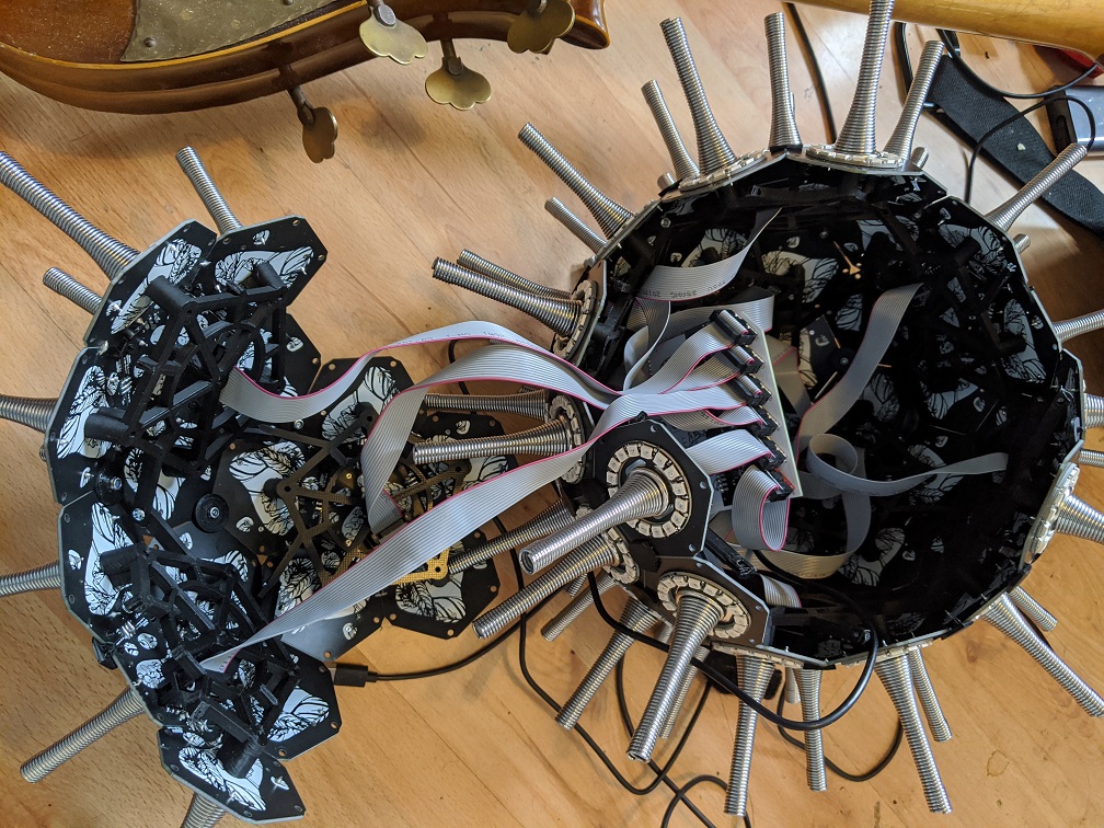
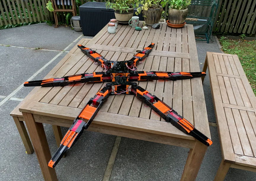
German designer and artist Alex Rex has created many installations combining sound and electronics. One of his most recent projects, Aura, envisions what it would take to make a field of wooden rods sway in response to the notes from a piano, clarinet, or other instrument.
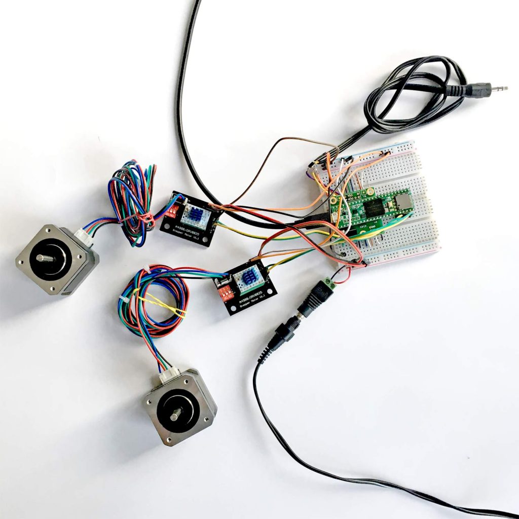
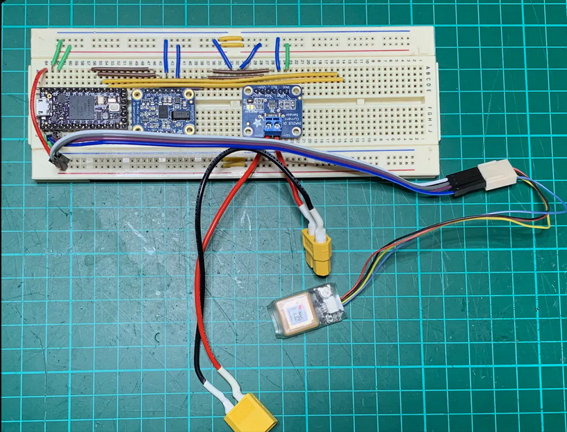
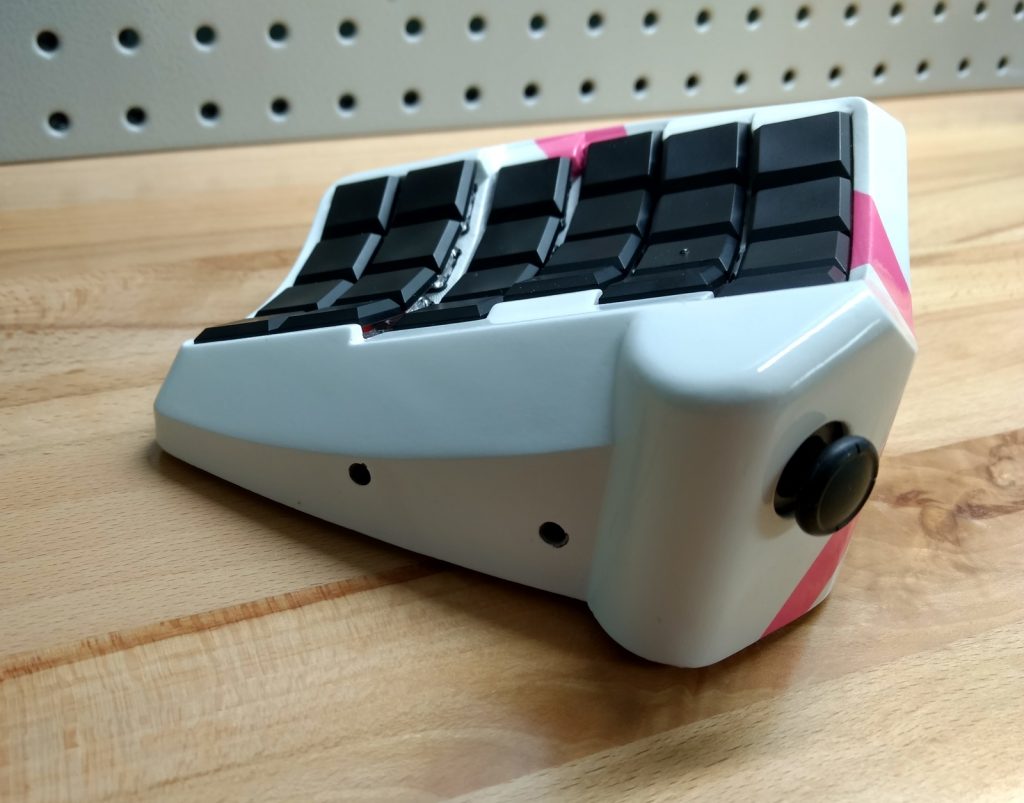
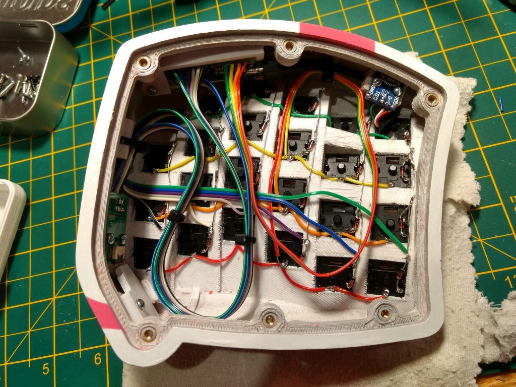
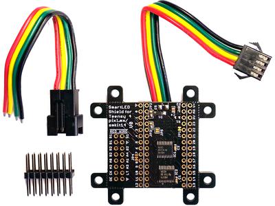
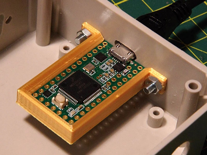
To realize the project, he uses a Teensy 3.5 and Teensy Audio Board to control a series of motors which direct the movements of wooden rods according to sound input from a microphone. The effect is a beautiful and whimsical installation where the surrounding rods appear to come to life in response to live music.
Not only is the project itself impressive, but even more impressive is Rex’s decision to use the project’s documentation as a platform for educating others about how to create musical electronic installations. He’s devoted an entire section of his website to tutorials which can help even beginners learn how to build reactive audio environments like Aura with both budget and materials in mind.
Rex’s tutorials are extremely thorough, including custom diagrams, parts lists, and step-by-step instructions with annotated source code. He takes things a step further by showing interesting ways in which sound can manipulate movement through examples of linear, rotational, and algorithmic models including videos of these models applied to outputs such as servos and LEDs.
You can view more of Rex’s projects including a machine which ignites and extinguishes matches and an exploration into alternative materials for producing vinyl records on his portfolio website.


