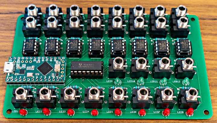
Sebastian Tomczak has improved his USB MIDI device from 8 gate and 16 CV outputs to 12 gate and 16 CV outputs.
This handy device has 16 control voltage (CV) outputs and 12 gate outputs. USB MIDI channels 1 – 8 are mapped to CV outputs 1 – 16 for pitch and velocity, and gates 1 – 8 for note on and off events. Gates 9 – 12 are mapped to note on and off events only on channel 9, and also will send a sync and transport signal based on MIDI clock messages if received.
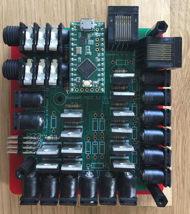
Bryan Jacobs of Knick Knack Sound built PhOut12, a motor shield controlled through USB-MIDI.
The PhOut12 allows software traditionally used for music to control motors. The board can control up to 12 DC motors, solenoids, or relays, and up to four servos. It also has a couple of inputs for sensors, pedals, or knobs. This versatile board offers a lot of options for adding sound control to your art project.
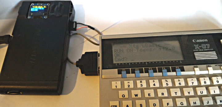
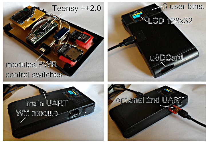
Franck Galliat has developed XtsTinyBasicPlus to make it run on a Teensy ++ 2.0 and connect to a Cannon X-07 hand held computer.
XtsTinyBasicPlus is a fork of TinyBasic. This version features support for an SSD1306 LCD screen, a uSD card reader, WiFi using the ESP8266 module, and 2 serial ports. It can act as a little http server to execute an auto-script that outputs to a web browser.
Some additional information can be found on this blog page.
Ali Afshar (alialiali on the forum) built a chordboard – a nifty synth project that includes a drum sequencer.
Ali describes this labor or love project as playing the major keys of piano with the ability to change the key and mode. It’s pretty easy to play and get a decent result. It also features a drum sequencer, strings, chords, and other stuff. The interface uses the oh so satisfying Cherry MX keys that have LEDs in them and a few pots to control things like tempo.
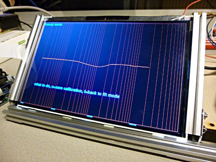
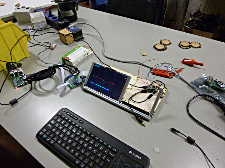
Marcell Marosvolgvi made an audio analyzer using a Teensy 3.2 and Audio Shield.
This project uses a Teensy 3.2 to generate a sine wave and send the output to an audio shield. Using a external loop, the data is fed back into the input of the shield and read by the Teensy and analyzed. The data is then sent to a Raspberry Pi for graphing and displayed on a 7″ TFT display.
This article was originally published in 2011 (archive.org link) on the DorkbotPDX site. Since then, the DorkbotPDX blog section has vanished. I’m reposting it here, to preserve the info. Even though LED strips are far more popular today than el wire, maybe this old info and code might still be useful? What follows is the original text from June 2011, with as many links updated as possible.
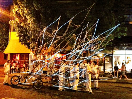
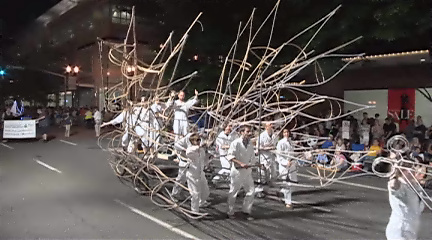
The lighting wasn’t very bright, but there were 114 computer controlled circuits. It was really the only float in the whole parade where the lights “did something” (Robin’s description). Indeed they blinked and faded in lots of complex patterns.
Laurence talked with Steve who’s a Dorkbot regular, who put her in touch with Mykle. Of course, Mykle’s interested in all types of lighting, and he posted it to the mail list on April 22. We all met up for the first time on May 9th and agreed on a rough plan involving a number of the Sparkfun el wire controller boards. All the el wire and controllers arrived on Friday May 13, the day Hand-Eye held a big party to celebrate the launching of the project, or something like that.
I did the electronics and software design part from the 14th to the 19th, and dropped off 2 working controllers and picked up lots of parts that were ordered on the 16th and had just arrived.
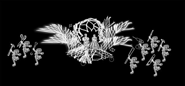
Originally Mykle and I had planned to use a perl script (which Mykle would write) to convert an XML export of Laurence’s Adobe After Effects animation (eg, the one you see in that video on Vimeo).
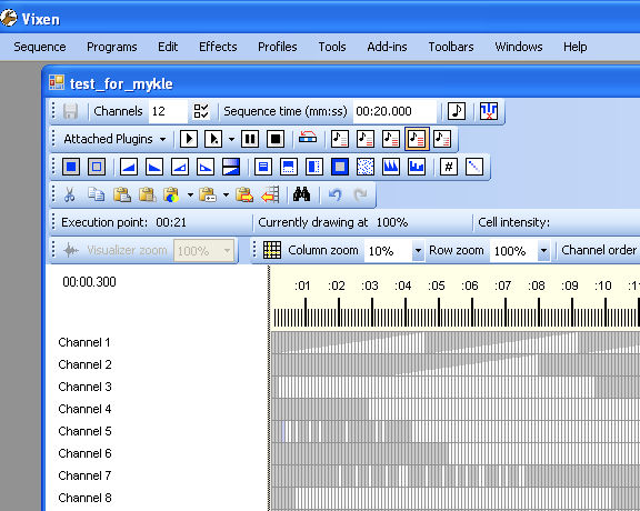
Vixen comes with plugins to communicate with a number of controllers people have created, and one of them looked particularly promising…. the Renard protocol. Several controllers have been made with PIC chips to control ordinary incandescent lighting. None were available for el wire, but the protocol allowed plenty of channels and didn’t require super fast baud rates, and supported 255 brightness levels. So I decided to just program the Sparkfun controllers to accept Renard input.
The Sparkfun el wire controllers were very problematic, but they were pretty much the only off-the-shelf board available. If I had to do this all over again, I would NOT recommend them. I’d make my own.
Here is the firmware I wrote for the Sparkfun boards. It allows each board to be any 8 channels, between 1-8 to 113-120, by placing jumpers on the header on the left side of the board. The boards don’t come with this header… I added to to each of them. Here’s how the jumpers configured each board.
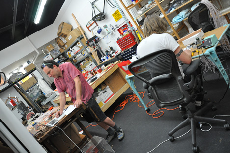
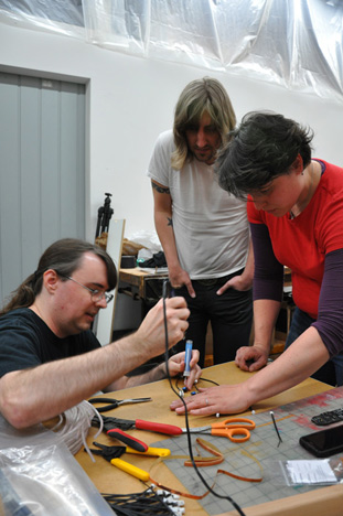
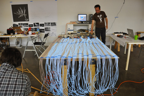
So, with 2 boards talking Renard protocol, on May 20th Laurence began a series of soldering parties. Here’s photos from the first soldering session, held at Hand-Eye Supply’s workshop.
(yup, that’s me soldering in this next photo… though I can’t recall what it was for, maybe a posed shot?)
Here’s a photo with a test (done a few days later) with just those first 2 boards. For about a week, only these first 2 boards were working while I modified all the others.
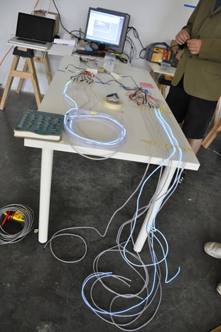
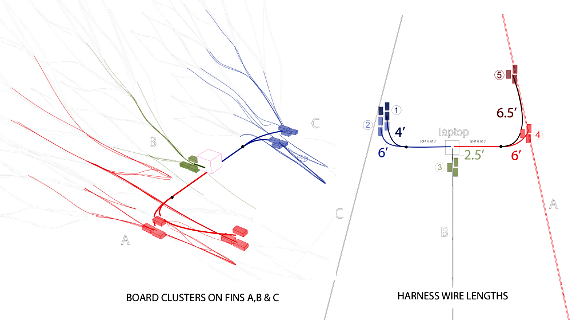
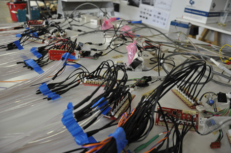
Mykle began work on a cable harness that would distribute data from a laptop running Vixen to all the el wire controller boards… 15 of them. Here’s a diagram of the harness design.
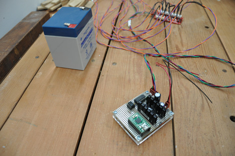
As you can see, the controllers are located in clusters. I mage a transmitter boards, using a Teensy 2.0 running the USB to Serial sketch, on a little hand-wired board with an opto coupler (who wants to hook a nice Mac laptop to a system of 15 high voltage el wire inverters?) and a 5 volt power supply, and buffer with poor-mans slew rate limiting (resistor-capacitor filter) to drive the long cable.
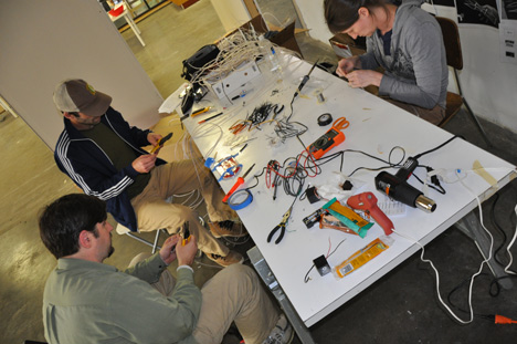
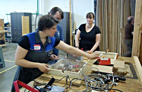
Somewhere shortly after the 20th, construction moved to ADX – which is a great space for building up a big project like this.
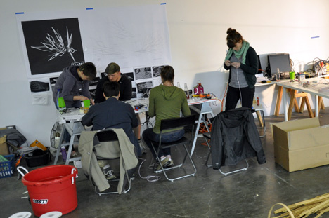
Here’s a photo of one of the early soldering parties at ADX.
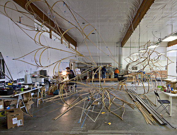
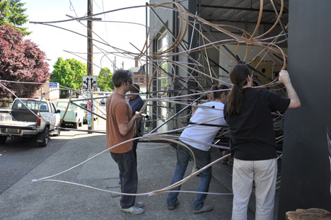
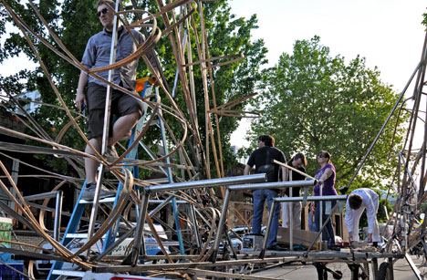
Here’s a photo from May 29th, as the bamboo pieces were starting to be assembled, and the steel which would be welded into the entire frame of the float had just arrived…
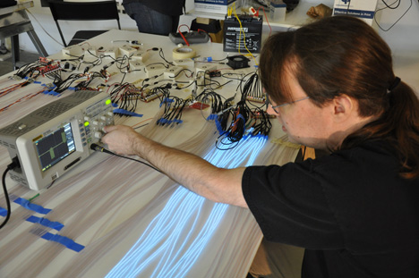
The electronics were all delivered on May 23rd for a full system test. There was a last minute problem with the cable, so only 2 boards were able to receive communication on the 23rd. Here’s that test, where I’m checking to see if the Sparkfun boards are having more troubles.
Mykle made some changes to the cable, and on May 24 the entire electronics package was verified to be working. I believe this was the only time, except for only an hour before the parade, where all the el wire was actually hooked up!
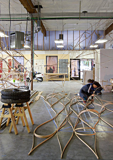
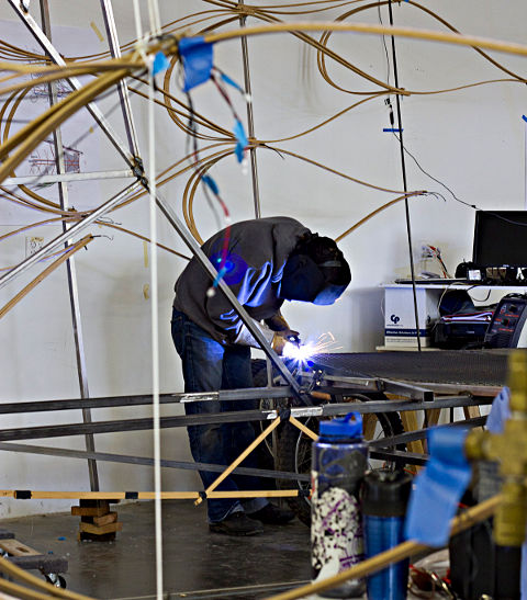
Building a float is a lot of work!!! I wasn’t really involved in the construction much, until the weekend of the parade. Laurence had quite a crew of dedicated volunteers, many of them students from the art institute. They put in a lot of work building the whole thing.
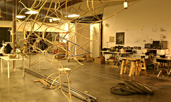
Not only did they build a huge number of these flowing structures from bamboo, but the entire frame of the float was welded together from raw steel. Pretty amazing. I wasn’t involved in any of this part. These photos were taken by ADX.
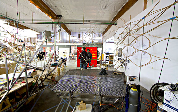
I stopped by on Thursday, June 2nd (2 days before the parade), and June 3rd (the night before, while ADX was having a huge grand opening party). Robin & I met there, I dropped off some parts and we had dinner out. Robin being so understanding about projects like this was ok with me staying there after our dinner out and working on it pretty late.
Here we are right before going out to dinner, and Robin’s really hungry and waiting while we try to figure out how the electronics will attach!
I went by Saturday (the date of the parade) and helped from about noon until the parade. Most of the lights were on the float, but none wired to the controllers, which had just been mounted that morning! I spent much of the time getting Mykle’s cable connected, and one of the groups of controllers had to be remounted for the cable to reach. It’s amazing how many little things all need to be solved.
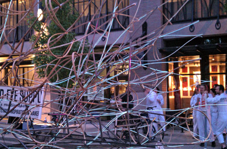
As things wrapped up at ADX late in the afternoon, we lit up the lights for the first time actually on the float, and it was indeed an awesome moment seeing it was indeed going to work, even if less than half had been wired in by that point.
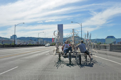
Getting the float from ADX to the parade staging are was another adventure… one for some else to write…….. Here’s a photo of the last part I saw at ADX, as it was being wheeled out onto the street to be (somehow) attached to a truck.
I actually left as they were hooking it to a truck to go meet up with Robin in NW for dinner near the parade. The brought it across the river to the parade staging area while Robin and I had dinner.
We both helped, and in those last few hours and amazing number of wires were all attached…. Beer was consumed too. 🙂
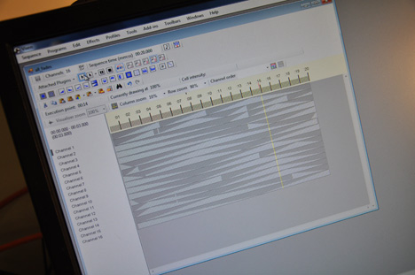
Tobias had created a number of sequences in Vixen. Sadly, there hadn’t been any time to test them with the wires attached, and efforts to map out which wires were on which channels just weren’t feasible in the daylight. El wire just isn’t really bright. Still, it was pretty impressive, if much more randomly flashing than the animations Laurence had originally envisioned.
With everything in place, Robin and I left and walked a few blocks to the beginning of the parade and set up a couple camping chair Robin had packed. We had a pretty good view.
Just as the parade was starting and the first couple (of many) marching bands went by, my phone rang. The computer had crashed and the float wasn’t working. I ran back. It was a mac and Windows was running in a virtual machine, so at least the host OS was fine. Somehow Windows had crashed. Some fiddling, plugging in to the different ports and installing drivers fixed the problem.
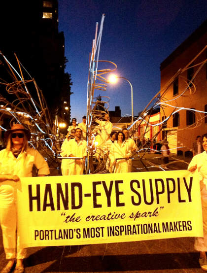
I returned to Robin and as the parade went by, I was a little worried it wasn’t dark enough for the el wire. Luckily, Hand-Eye Supply was #82 in the parade, so they entered around 9:30 and it was quite a bit darker by them. It still wasn’t nearly as bright, but the lights did flash and fade in lots of patterns.
With so much coming together so quickly in just a few weeks, with all those wires connected within hours of the parade, I was pretty amazed it worked. Then today, Mykle emailed the KGW story that Hand-Eye Supply’s float won the 1st place award!! 🙂
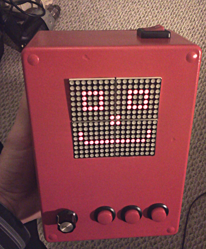
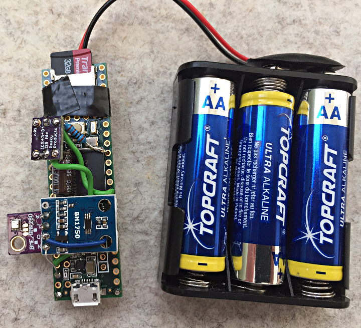
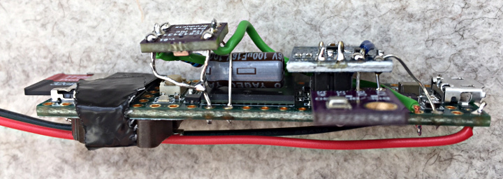
Frank (forum user DD4WH) made a microSoundRecorder to log both audio and environmental data to an SD card.
The recorder uses a BME280 sensor to log temperature, air pressure and humidity, and a BH1750 sensor to log light intensity. It also includes a digital microphone to capture audio.
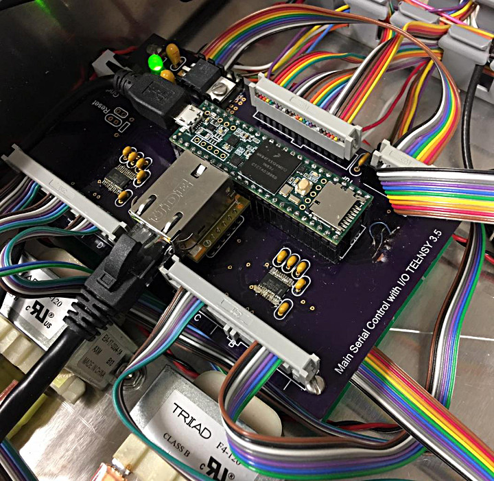
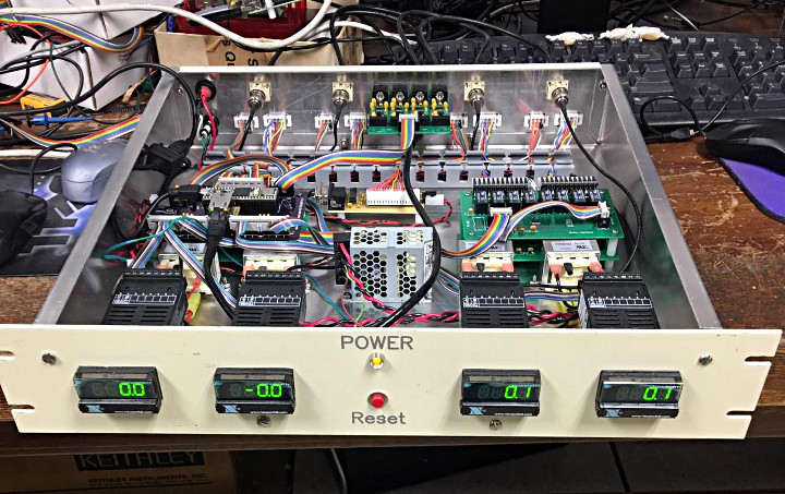
Tim Cowden (Cowlander on the forum) has been using a Teensy 3.5 to build a controller for a cyclotron particle accelerator.
As part operations staff at the Cyclotron Institute at at Texas A&M University, Tim is responsible for the control systems. He’s been working on replacing the Rabbit 3200 embedded controller they’ve been using with a Teensy 3.5. The Teensy 3.5 has proven to be a good fit when combined with a Wiz850 network module.
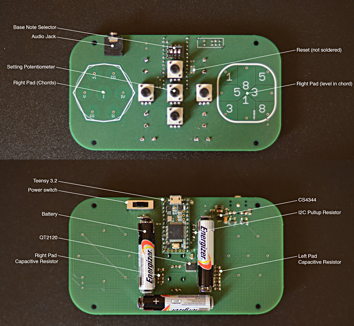
Benjamin Poilve (BenIP on the forum) has made a neat little hand-held instrument, Synthetica.
Ben came up with an idea to make a musical instrument to play around with chord progressions as a way to experiment with music composition. He came up with Synthetica, a handheld synthesizer. Synthetica is played using capacitive touch with one hand selecting a chord and the other hand selecting a note. With some help from the forum he got his project up and running.
Some of the features include pots to control:
Delay time
Delay feedback
Octive detaune
LFO frequency
LFO detune
LFO mix
Code for the project has been published on GitHub.