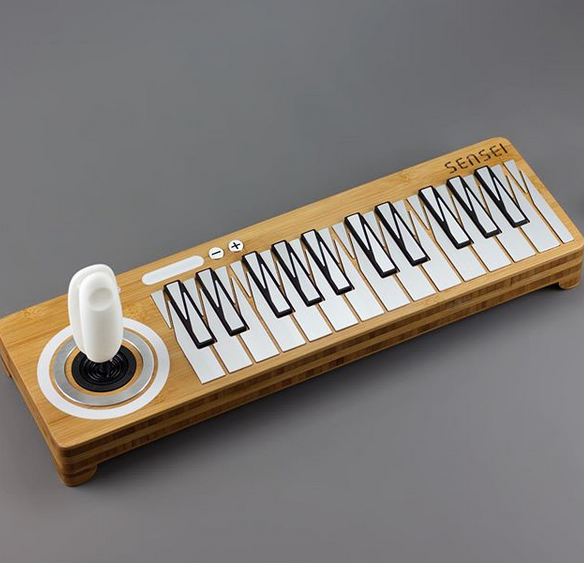
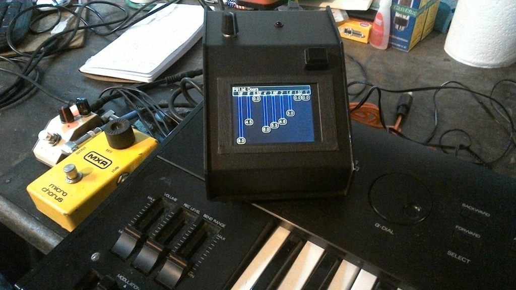
The Neutron Orgone Accumulator is a unique complex digital oscillator built by J.Matheson who uses usernames Neutron7 and jakplugg.
Basic operation involves the mixing of a core of three waveforms which can be dynamically scanned. Modulation and effects can be applied to produce sound. The first version of the build is documented on the Muffwiggler forums, with a beta version of the build guide available as a PDF.
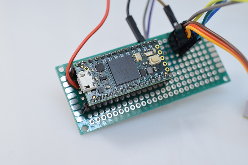
There is a high performance version of 2.0 firmware designed to work with Teensy 3.1 at 144Mhz overclock. It will increase the sample and calculation rate from 50khz to 90.909khz. Details of the newer version and relevant code can be found on Github.
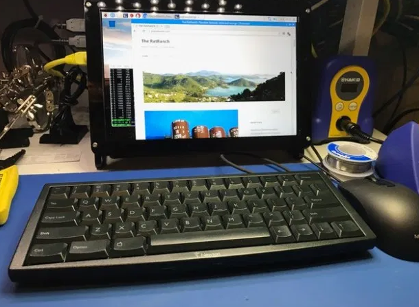
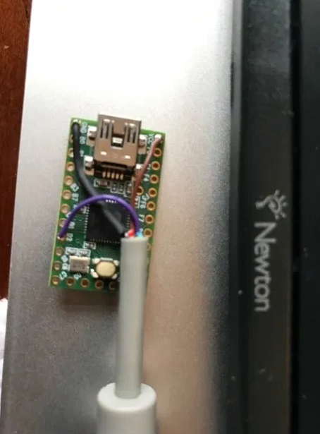
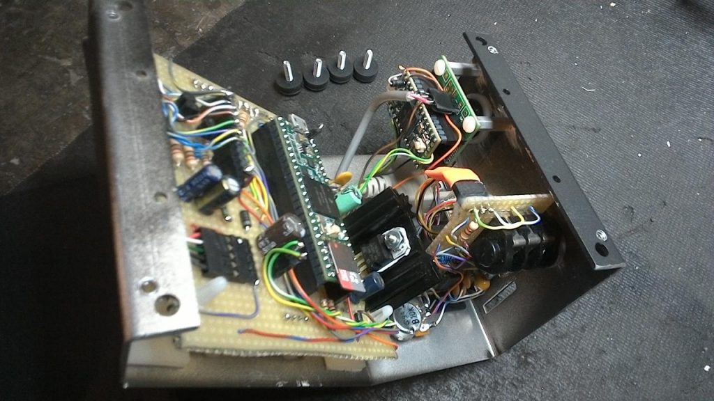
Steve Batz made a build of the module and documented the process in detail on his blog and in this video on his Facebook page.