Teensy® 3.2 Development Board
|
|
TEENSY32 | Teensy USB Board, Version 3.2 |
Update: October 3, 2025: We will have a limited number of Teensy 3.2 available starting Monday, October 13 at 10am US Pacific time.
Update: July 3, 2025: We will have a limited number of Teensy 3.2 available starting Monday, July 7 at 10am US Pacific time. Limit 5 per person.
Update: January 27, 2025: Julien from Inorevia has 100 leftover unused Teensy 3.2 boards for sale. Contact Julien directly by email as mentioned in the forum message. Please understand PJRC is not party to this sale, we're only providing this update to help you connect with Julien if leftover Teensy 3.2 are needed.
Update: May 30, 2024: bboyes has about 400 leftover unused Teensy 3.2 boards for sale. Contact bboyes directly by email as mentioned in his forum message. Please understand PJRC is not party to this sale, we're only providing this update to help you connect with bboyes if leftover Teensy 3.2 are needed.
Update: October 25, 2023, 10:00am: Ornament and Crime first Phazerville firmware beta with experimental support for Teensy 4.0 and Teensy 4.1. If you missed out on Teensy 3.2 needed for Ornament and Crime, now you can use Teensy 4.0.
Update: October 19, 2023, 10:00am: About 97% of the final Teensy 3.2 batch has sold. We expect to run out of stock today.
Update: October 18, 2023, 10:00am: About 81% of the final Teensy 3.2 batch has sold.
Update: October 17, 2023, 9:00am: About 66% of the final Teensy 3.2 batch has sold since we opened ordering 24 hours ago.
Update: October 16, 2023, 2:20pm: Since 9am approximately half of this final Teensy 3.2 batch has sold. The rate of new orders has slowed since this morning.
Update: October 11, 2023: The buy button will go live on this page October 16 at 9am, US Pacific time zone. Limit 4 per person. In other news, Ornament and Crime Phazerville firmware has merged a Teensy 4.x SPI driver which is the beginning of Teensy 4.x starting to basically work on O_C. Much work remains, but it's safe to say Ornament and Crime will continue (and likely develop a lot more capability) on Teensy 4.0 & 4.1. Existing O_C hardware (except VOR) will be able to use Teensy 4.0. We don't recommend stockpiling Teensy 3.2 for Ornament and Crime, because it doesn't have enough memory for all O_C apps & applets. Teensy 4.0 does.
Update: October 4, 2023: This will be the final batch of Teensy 3.2. It will be discontinued after this October batch is sold. A couple weeks ago we talked with people at NXP who wanted to help. But they simply can't. It is a painful decision for us to discontinue Teensy 3.2 after 11 years (or really 10 of those years it was readily available).
Update: September 20, 2023: Synth DIY builders - we are working on next-gen Ornament and Crime hardware using Teensy 4.1, with release likely by December. The new hardware will offer a massive increase in capability and enough memory for all O_C apps in a single firmware.
Update: September 18, 2023: The final Teensy 3.2 batch is now in production. Best estimate is we'll start shipping on October 16. A limit of 4 per person will apply. Teensy 3.2 will be discontinued after this final batch is sold. To request more than 4, simply reply to any email from prior purchases. We must know about your application and see documentation of prior purchases. Without detailed info, the quantity 4 limit will apply. We highly recommend migrating to Teensy 4.0. For audio projects needing the DAC pin, we recommend using either MSQ with resistor-capacitor filter, the PT8211 DAC.
|
Sections On This Page:
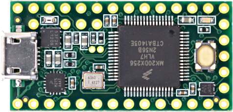
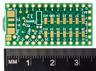
Photos
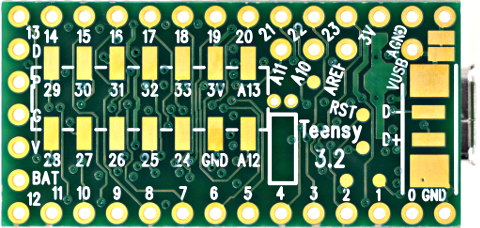
Back Side:
Specifications
- ARM Cortex-M4 at 72 MHz
- 256K Flash, 64K RAM, 2K EEPROM
- USB device 12 Mbit/sec
- 34 digital input/output pins, 12 PWM output pins
- 21 analog input pins, 1 analog output pin, 12 capacitive sense pins
- 3 serial, 1 SPI, 2 I2C ports
- 1 I2S/TDM digital audio port
- 1 CAN bus
- 16 general purpose DMA channels
- RTC for date/time
Software
- Arduino IDE + Teensy boards add-on
- Arduino's IDE software with the Teensy Boards add-on is the primary programming environment for Teensy. The add-on is installed using Arduino's Boards Manager. Teensy boards add-on includes a large collection of libraries which are tested and optimized for Teensy. Other libraries may be installed manually or by Arduino's library manager.
- Visual Micro
- Visual Micro allows use of Microsoft Visual Studio to program Teensy and many other boards. Only Windows is supported. Visual Micro is commercial paid software.
- PlatformIO
- PlatformIO IDE is a cross platform development environment with many advanced features. Windows, Linux and Macintosh are supported.
- Command Line with Makefile
- Makefiles for non-graphical use are provided with the Teensyduino installer.
- Teensy 4.x: {Arduino}/hardware/teensy/avr/cores/teensy4/Makefile
- Teensy LC & 3.x: {Arduino}/hardware/teensy/avr/cores/teensy3/Makefile
Processor
- Performance
- (info here)
- Memory Interface
- Dual 32 bit buses allow the processor to simultaneously fetch instructions and transfer data.
- Digital Signal Processing
- DSP extension instructions accelerate signal processing, filters and Fourier transform. The Audio library automatically makes uses of these DSP instructions.
Pins
Teensy 3.2 has a total of 34 input/output signal pins. 24 are easily accessible when used with a solderless breadboard.This pinout reference card comes with Teensy 3.2.
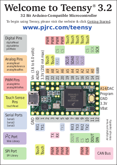
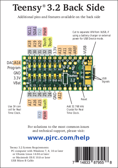
Pinout Card Files:
Front Side (PDF) /
Back Side (PDF)
Digital Pins
- Digital Input Pins
- Digital pins may be used to receive signals. Teensy 3.2 pins default to a low power disabled state. The pinMode function with INPUT must be used to configure these pins to input mode. Then the input may be read with digitalRead. Teensy 3.2 pins accept 0 to 5V signals. The pins are 5V tolerant. Do not drive any digital pin higher than 5V.
- Input Pullup & Pulldown Resistors
- All digital pins have optional pullup and pulldown resistors. These are used to keep the pin at logic HIGH or logic LOW when it is not being actively driven by external circuity. Normally these resistors are used with pushbuttons & switches. The pinMode function with INPUT_PULLUP or INPUT_PULLDOWN must be used to configure these pins to input mode with the built-in resistor.
- Pin Change Interrupts
- All digital pins can detect changes. Use attachInterrupt to cause a function to be run automatically. Interrupts should only be used for clean signals. The Bounce library is recommended for detecting changes on pushbuttons, switches, and signals with noise or mechanical chatter.
- Digital Output Pins
- All digital pins can act at output. The pinMode function with OUTPUT or OUTPUT_OPENDRAIN must be used to configure these pins to output mode. The digitalWrite and digitalToggle functions are used to control the pin while in output mode. Output HIGH is 3.3V. The recommended maximum output current is 10mA.
- Pulse Width Modulation (PWM)
- 12 of the digital pins support Pulse Width Modulation (PWM), which can be used to control motor speed, dim lights & LEDs, or other uses where rapid pulsing can control average power. PWM is controlled by the analogWrite function. 3 groups of PWM can have distinct frequencies, controlled by the analogWriteFrequency function.
- Slew Rate Limiting
- This optional feature greatly reduces high frequency noise when long wires are connected to digital output pins. The rate of voltage change on the pin is slowed. The extra time is only nanoseconds, which is enough to lower undesirable high frequency effects which can cause trouble with long wires.
- LED Pin
- Pin 13 has an orange LED connected. The LED can be very convenient to show status info. When pin 13 is used as an input, the external signal must be able to drive the LED when logic HIGH. pinMode INPUT_PULLUP should not be used with pin 13.
Analog Pins
- Analog Inputs
- 21 pins can be used an analog inputs, for reading sensors or other analog signals. Basic analog input is done with the analogRead function. The default resolution is 10 bits (input range 0 to 1023), but can be adjusted with analogReadResolution. The hardware allows up to 16 bits of resolution, but in practice only up to 13 bits are normally usable due to noise. More advanced use is possible with the ADC library. Analog inputs can also receive audio signals with the Audio library, but the sound quality is lower than using the Audio shield.
- Analog Range & Reference Voltage
- The AREF pin is used to set the analog input range. By default, AREF is 3.3V due to a resistor. External shunt-type reference chips may be connected for lower reference voltage. Or analogReference(INTERNAL) may be used to set the analog range to 1.2V.
- 5 Volt Tolerance
- Analog input pins which have digital capability are 5 volt tolerant, even when the digitial features are not used. When driven higher than AREF, these pins measure the maximum reading. Analog input pins without digitial (A10, A11, A12, A13, A14) are not 5V tolerant. Do not drive analog-only pins higher than 3.3V.
- Differential & Programming Gain Amplifiers
- Pins A10 & A11 and A12 & A13 have a differential amplifiers.
- Analog Comparators
- These comparators allow an analog signal to be converted to digital, with a precisely defined voltage threshold for logic low versus high.
- Analog Outputs / Digital To Analog (DAC)
- One true analog output DAC is present on pins A14. This may be used with analogWrite, or the Audio library.
- Capacitive Touch Sensing
- 12 pins can measure ground-coupled capacitance. The touchRead(pin) function is used. When Teensy GND is connected to earth ground, or to a conductive enclosure the user holds, these pins may be connected to electrodes to for a touch sensitive user interface. Touch sensing can also be done on other pins with the CapacitiveSensor library, but the built in hardware on these 12 pins is more accurate and much faster.
Communication
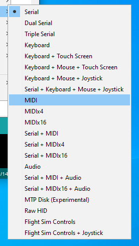
Tools > USB Type menu configures the type of USB device Teensy will implement.
- USB Device
- Teensy's primary communication is its main USB port, which operatates in USB device /
peripheral mode at 12 Mbit/sec speed. The Teensyduino software supports many different
types of USB communication to your PC or Mac, selected by the Tools > USB Type menu.
Several of these devices types may be used simultaneously.
- Serial - Seen by your computer as a COM port (Windows) or serial device (Mac, Linux), Serial is the default and most commonly used communication type. Bytes are transfered in both directions at maximum USB speed (baud rate settings are ignored). Teensyduino has highly optimized code to allow fast USB serial data transfer. While normally used with the Arduino Serial Monitor, Teensy's USB Serial mode is compatible with software designed for serial ports, like CoolTerm. On Teensy, the seraild devices is accessed as "Serial". In the Dual & Triple Serial modes, the additional serial devices are "SerialUSB1" and "SerialUSB2".
- Emulated Serial - The USB Type settings lacking Serial use a HID interface to emulate serial. In these modes, your PC or Mac will not detect a COM port or serial device, but you can still use Serial.print() to send text to the Arduino Serial Monitor.
- MIDI - Musical Instrument Device. MIDI is often used to interface knobs, sliders and buttons to music & sound control software. MIDI messages may be sent in both directions. Teensyduino's MIDI is "class compliant" for compatibility with Macintosh, Linux, and Windows using only built-in drivers. The MIDIx4 & MIDIx16 modes provide 4 or 16 virtual MIDI ports / cables. The MIDI device name seen by your computer may be customized.
- Audio - Bi-directional stereo audio streaming, seen by your computer as a USB sound card. Using your computer's sound preferences, programs which play sound can stream to Teensy, and programs which record or process sound can receive, as if you were using a USB microphone. USB Audio is meant to be used together with the Teensy Audio Library, allowing your computer's sound to integrate with any audio processing system you design on Teensy.
- Keyboard - Standard 104 key USB keyboard. Programs can transmit keystrokes to your computer, allowing control of nearly any software. Media control keys (play, pause, volume, etc) may also be used. Many non-US keyboard layouts are supported, using the Tools > Keyboard Layout menu.
- Mouse - A special USB mouse is emulated. Both relative motion of a normal mouse, and absolute screen position similar to a digitizer pen can be sent to your computer. Mouse buttons and scroll wheel are also supported.
- Joystick - A joystick / game controller with 6 axes (X, Y, Z, Zr, Slider1, Slider2), 32 buttons, and 1 hat switch are supported. The Joystick type is useful for controlling games or other software which responds to a joystick.
- Touchscreen - Emulates a touchscreen capable of detecting up to 10 finger positions.
- MTP Disk - Media Transfer, seen by your computer as a phone or camera which shares files.
- Flight Sim - Allows integration with the X-Plane flight simulator software. Variables and controls within the simulator are linked to variables in your code running on Teensy.
- Raw HID - Allows communicating 64 byte messages with custom written software on your computer.
- Serial
- 3 serial ports allow you to connect serial devices, such as MIDI, GPS receivers, DMX lighting, ESP wireless modules, etc. All 3 serial port are fully independent and can transfer data simultaneously. None are shared with USB (as is done on some Arduino boards). Serial1 & Serial2 include FIFOs for better performance at high speed baud rates.
- I2C
- 2 ports for I2C (signals SDA & SCL) allow connecting a wide variety of chips which use I2C communication. The Wire library is used for I2C. Each I2C chip connected to the same SDA/SCL wires needs a unique address. Multiple I2C ports allow you to easily use more than 1 chip with the same address. All I2C ports support 100, 400, and 1000 kbit/sec speeds.
- SPI
- 1 port for SPI (signals MOSI, MISO, SCK) allow connecting higher speed chips, SD cards, and displays which use SPI communication. The SPI library provides software support for SPI. A FIFO for higher sustained speed transfers is included. Each SPI chip requires a chip select (CS) signal. Most libraries using SPI can use any digital pin. The SPI ports provide special hardware controlled CS pins, which are used by specially optimized libraries for higher performance.
- CAN
- 1 port for CAN bus allow connecting to automotive & industrial control systems which use CAN communication. A CAN transceiver chip must be added to complete the electrical interface between Teensy 3.2 and the CAN bus.
Displays
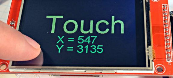
ILI9341 Color TFT Display The best supported display for Teensy 3.2
- ILI9341 320x240 Color TFT
- These displays are the best supported on Teensy 3.2, with multiple high performance libraries for fast updates speed. ILI9341 is usually the best display to use, due to superior software support.
- ST7735 Color TFT
- These displays are slightly smaller and lower resolution than ILI9341. Highly optimized libaries for ST7735 & ST7789 allow these to also perform very well.
- SSD1306 Monochrome OLED
- These small displays are very popular and well supported.
- Other Displays
- Almost all displays with Arduino libraries work on Teensy 3.2.
Audio
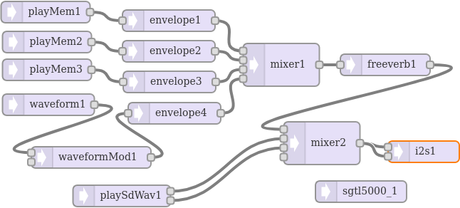
Audio Design Tool makes it easy to create an audio processing system which streams sound while your program runs.
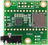
Audio Shield converts I2S digital audio to analog stereo input & output.
- I2S / TDM
- Most commonly used with the audio shield, 1 digital audio port can simultaneously transmit and receive up to 4 audio channels using I2S protocol, or up to 16 channels using TDM. Alternately, a special format used by inexpensive PT8211 DAC chips can be used.
- S/PDIF
- The I2S port may be used to transmit S/PDIF. Receiving S/PDIF is not supported on Teensy 3.2, but Teensy 4.0 & 4.1 can receive S/PDIF.
- Analog Input (ADC)
- 1 or 2 analog input pins may be used for audio inputs. These may be used simultaneously with the other audio inputs & outputs.
- Analog Output (DAC)
- The DAC output pin can transmit audio. This may be used simultaneously with the other audio inputs & outputs.
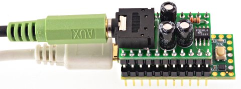
PT8211 is the least expensive DAC for good quality stereo signal output
Lights & LEDs
OctoWS2811 Library controlling 1920 WS2812B RGB LEDs at 30 Hz refresh rate
- WS2812B / NeoPixel
- Two high performance non-blocking libraries support use of WS2812B LEDs. OctoWS2811 transmits 8 outputs in parallel, allowing up to 8800 LEDs to be refreshed at up to 30 Hz video rate. WS2812Serial transmits a single output, but up to 5 instances may be used. Non-blocking transmission uses DMA to transmit automatically, while your code is able to continue running. This much more allows complex animations or efficent communication than traditional blocking.
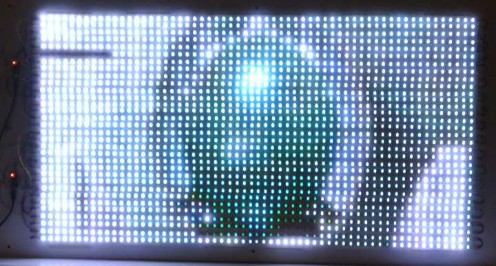
- SmartMatrix & SmartLED Shield for HUB75 RGB LED Panels
- SmartLED Shield (version 4) enables Teensy 3.2 to drive high-quality graphics to HUB75 RGB LED panel arrays (from 32x16 up to 64x64 pixels). The SmartMatrix library makes it easy to draw basic graphics, create scrolling and static text, draw beautiful patterns using FastLED, and play animated GIFs on the panel. SmartMatrix uses Teensy 3.2's special features to send graphics data with minimal CPU usage, so you can use the processor to do other tasks in parallel such as SPI communication, file decoding, or complex rendering.
- DMX Lighting Control
- Serial1 & Serial2 may be used for efficient communication with DMX lighting controllers.
- RGB LEDs
- Ordinary LEDs by be variable-brightness controlled by PWM, or the SoftPWM & ShiftPWM libraries.
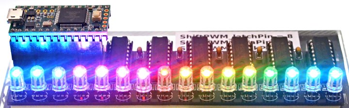
ShiftPWM controlling 16 RGB LEDs using six 74HCT595 chips
Timing
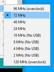
Tools > USB Speed menu configures the speed Teensy 3.2 will run your code.
- Crystals & Clock Generation
- A 16 MHz crystal is the basis for the system clock and most peripherals. A phase locked loop (PLL) increases the 16 MHz up to the system clock speed.
- Interval Timers
- 4 timers are dedicated to running a function at precisely timed intervals. These are configured using the IntervalTimer class.
- PWM Timers
- 4 timers control PWM pins,
or may be used for other timing functions.
Normally these timers are accessed with analogWrite or libraries, but they
have many very advanced features which may be accessed by direct hardware
register use.
- FTM0 - Controls PWM pins 5, 6, 9, 10, 20, 21, 22, 23. Used by AltSoftSerial library and PulsePosition library.
- FTM1 - Controls PWM pins 3, 4.
- FTM2 - Controls PWM pins 25, 32. Used by OctoWS2811 library.
- Watchdog Timer
- This timer is meant to reboot Teensy if your software crashes or gets stuck. Once started, the watchdog timer must be periodically reset. If the software stops resetting the timer for too long, Teensy reboots.
- Special Timers
- These extra timers allow delays, analog sample rate timing, carrier modulation,
and other special timing tasks to be performed, without consuming any of the
normal PWM-oriented timers.
- PDB - Delay timer, used by Servo library, and Audio library for ADC input & DAC output.
- LPTMR - Generic Timer, used by FreqCount library.
- CMT - Carrier Modulation Timer, used by IRRemote library.
- Cycle Counter
- A 32 bit counter increments every CPU clock cycle (72 MHz). ARM_DWT_CYCCNT may be read by programs to precisely measure short time duration time.
- SysTick
- This system timer generates an interrupt every millisecond. Most of the software timing features use this Systick timer.
- Software Timing
- Many common timing requirements can be met using the software timing features.
- delay(), delayMicroseconds(), delayNanoseconds() - Simple delay for milliseconds, microseconds, or nanoseconds.
- elapsedMillis, elapsedMicros - These C++ classes act as a variable which automatically increments ever millisecond or microsecond. These can be written or modified as needed, which greatly simplifies implementation of repetitive tasks, measuring elapsed time, inactivity timeouts, and so on. The number of these variable is only limited to the available memory.
- millis(), micros() - Stardard Arduino functions for the system time in milliseconds and microseconds.
- Real Time Clock - Date & Time
- The RTC keeps track of date / time. A 32.768 kHz crystal must be added to Teensy 3.2 to make the RTC work. The Time library is typically used together with the RTC. Teensy Loader automatically initializes the RTC to your PC's time while uploading. If a coin cell is connected to VBAT, the RTC will continue keeping time while power is turned off.
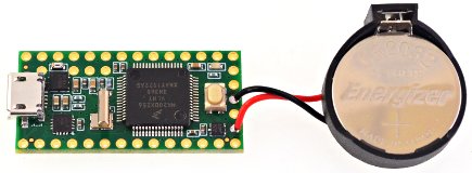
32.768kHz Crystal and CR2032 Coin Cell connected to VBAT allows Teensy 3.2 to keep date / time while power is off
Power
- USB Power
- Normally Teensy is powered by your PC or USB hub, through a USB cable. The USB power arrives at the VUSB pin, which is connected VIN and powers the entire board.
- VIN Pin
- When USB power is not used, 5V power may be applied to the VIN pin. Because VIN & VUSB are connected, power should not be applied to VIN while a USB cable is used, to prevent the possibility of power flowing back into your computer. Alternately, a pair of pads on the bottom side may be cut apart, to separate VUSB from VIN, allowing power to be safely applied while USB is in use. Be careful not to cut too deep, as the VIN wire runs through an internal layer of the PCB. If the trace is cut, see this forum thread on repairing a severed VIN wire.
- 3.3V Power
- Teensy 3.2 has a voltage regulator which reduces the 5V VUSB / VIN power to 3.3V for use by the main processor and most other parts. Additional circuitry may be powered from the 3.3V pin. The recommended maximum for external 3.3V usage is 250mA. When power is not applied to VUSB or VIN, it is possible to run by externally applying 3.3V power.
- AGND & GND Pins
- Teensy 3.2 has 3 GND pins and 1 AGND pin. The GND pins are the normal system ground. Digital signals and most applications should use GND. The AGND pin is meant only for the grounds from sensitive analog signals.
- Power Consumption
- (info here)
- Low Power Features
- (info here - Snooze library)
- VBAT
- A 3 volt coin cell may be connected to VBAT & GND to allow the RTC to keep track of date / time while power is off. The RTC also requires a 32.768 kHz added. A CR2032 type battery is recommended, though other 3V coin cells may also be used.
Memory
TODO: memory map diagram- Program / Flash Memory
- Teensy 3.2 has 256 kbyte of flash memory intended for storing your code. The flash memory can also store read-only variables and arrays.
- RAM
- 64K of memory is available for variables and data. Functions may also be placed in RAM using the FASTRUN keyword.
- EEPROM
- 2048 bytes of emulated EEPROM memory is supported. Special FlexNVM hardware allows this memory to be written without disruption to normal flash memory. The EEPROM library is typically used to access this memory. AVR libc functions may also be used.
- RTC RAM
- 32 bytes of memory are located within the RTC. If a coin cell is connected to VBAT, contents of this memory is preserved while power is off. The last 4 bytes are used by startup code to manage configuration of data/time, leaving 28 bytes available for general use.
- SD Card
- SD cards may be used via the SPI pins, using the SD library with SD.begin(cspin).
- SPI Flash
- Flash memory chips may be added using the SPI pins. These are supported by the SerialFlash and LittleFS libraries.
Programming
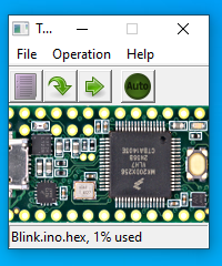
Teensy Loader Application
- Teensy Loader
- Programming of Teensy's flash memory is done by the Teensy Loader application. Normally the Arduino IDE or other software is used to compose code, and it automatically runs Teensy Loader as needed. If you have compiled code in HEX file format, Teensy Loader can be used stand-alone to write your HEX file into Teensy's flash memory.
- Automatic Software Entry to Program Mode
- While developing with Teensy, loading normally happens automatically after compiling your program. A "teensy_reboot" utility looks for your Teensy on all USB ports and sends a request (serial baud rate or HID feature report) to automatically switch to programming mode.
- Program Pushbutton / Pin
- If code previously written to Teensy is not listening for USB communication, automatic entry to programming mode is not possible. A physical pushbutton is provided to allow recovery from bad code. Pressing the button button puts Teensy into programming mode. It is not a "reset button" which restarts your program. The button is dedicated to recovery from bad code. A Program pin also allows external hardware to force entry to programming mode.
- Reset
- An active-low reset signal allows rebooting, which restarts the program loaded in Teensy's flash memory. This signal is located on the bottom side, on a small pad labeled "R".
- Bootloader Chip
- Teensy 3.2's bootloader is stored in a dedicated chip. All of the main chip's memory is available to your program. Upon power up, your program runs immediately. The bootloader does not run automatically at startup, as is done with most Arduino compatible boards. The physically separate chip keeps Teensy's bootloader separate from your code and prevents flash programming from being able to damage or erase the bootloader.
- Code Security
- For applications requiring code secrecy or security, the FSEC setting may be edited in Teensy's startup code. When code with FSEC set to secure mode is loaded, the Program button function changes to fully erase the flash memory when pressed.
Special Features
- Nested Interrupt Controller
- Priority nesting allows low latency for critical interrupts while lower priority interrupts are in use. Teensyduino's libraries utilize interrupt nesting with priority level defaults which allow many types of libraries to work well when used together.
- Direct Memory Access (DMA)
- Teensy 3.2 has a general purpose 16 channel DMA controller. Optimized Audio, LED and display libraries make uses of these DMA channels. A DMAChannel.h abstraction layer is provided. The USB device, USB host, SD card and Ethernet peripherals also have specialized DMA engines built in.
Technical Information
- MK20DX256 Manual - All the useful peripheral programing info
- MK20DX256 Datasheet - Only the electrical specifications
- Definitive Guide to ARM Cortex-M3 & Cortex-M4 (book) - ARM Processor low-level details
- RoHS Certificate of Compliance
Dimensions
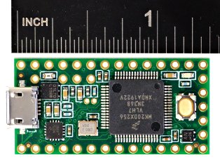
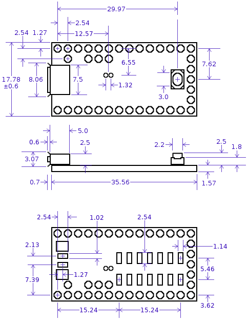
User contributed 3D CAD models may be available on the forum.
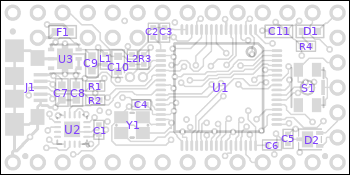
Schematic
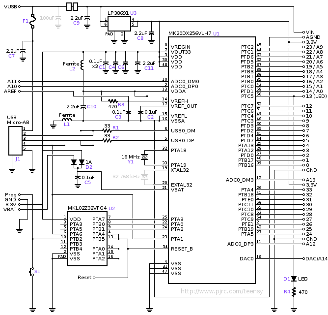
Component Locations