PT8211 Audio Kit for Teensy 3.x
SparkFun is now manufacturing Teensy products. You can buy directly at SparkFun.

|
PT8211_AUDIO_KIT | PT8211 Audio Kit for Teensy 3.x and Teensy 4.x |
PT8211 is a 16 bit stereo digital to analog converter (DAC) chip. The output is a line-level signal meant for amplified speakers, stereo receiver, mixer or amplifier. It is not meant to directly drive headphones or speakers.
This kit includes the PT8211 chip, bare circuit board, audio connector, 1 resistor and 4 capacitors. DIY soldering is required.
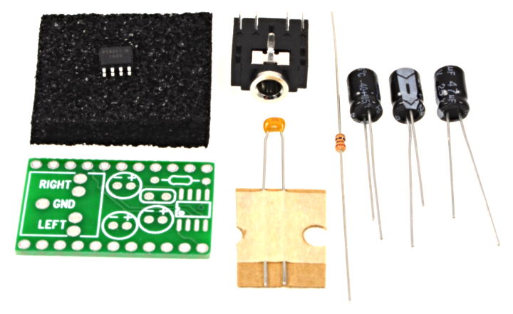
Teensy 3.2, Teensy 3.5, Teensy 3.6, pins, double insulator pins, and sockets are sold separately. This kit is not compatible with Teensy 2.0, Teensy++ 2.0 or Teensy LC.
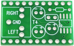
Update: We are now including 2 circuit boards with this PT8211 kit.
This new board brings the 3 signals to pins 7, 20, 21 used by Teensy 4.0.
If you are using Teensy 3.2, 3.5 or 3.6, solder the parts to the original
board, without text between the capacitors. If using Teensy 4.0, solder
with this new board which has "T4" printed between the capacitors.
Assembling The PT8211 Kit
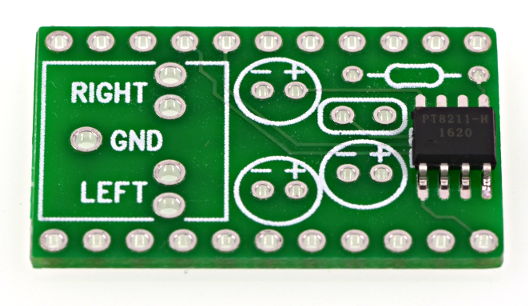
The first part to solder is the PT8211 chip. Apply a small amount of solder to 1 of the surface mount pads. Then using tweezers or needle-nose pliers, carefully align the PT8211 chip and heat the solder to "tack" it into place. Be careful to orient the chip correctly, matching the pin #1 dot on the chip with the dot printed on the circuit board.
With the PT8211 tacked into place, carefully solder all 8 pins. This is the most challenging part to soldering. A magnifier and bright light are highly recommended.
The 10 ohm resistor is next. Bend the leads and push it through the board. The resistor can be placed in either direction.
Then solder the 0.1 µF capacitor. Like the resistor, this part is not directional.
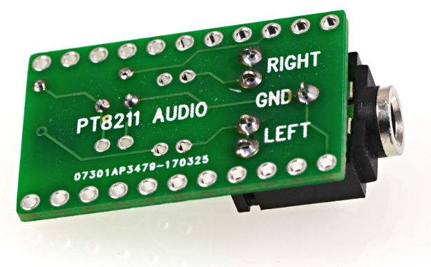
Solder the audio connector next. The board will tip at an angle, because this part is much taller. Solder one of the pins, then visually check the connector is aligned flush with the board. After you solder more than 1 pin, it's almost impossible to straighten. Finish soldering the rest of its pins once the fit is good.
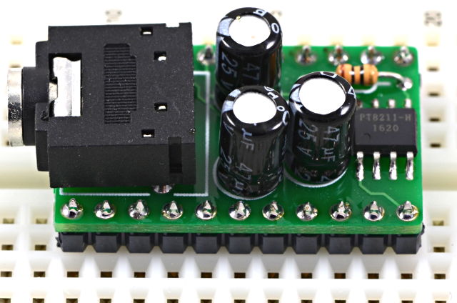
The three 47 µF capacitors are the last parts to solder. These are directional. Align the side with the negative marking towards the audio connector. The circuit board also has polarity markings to help.
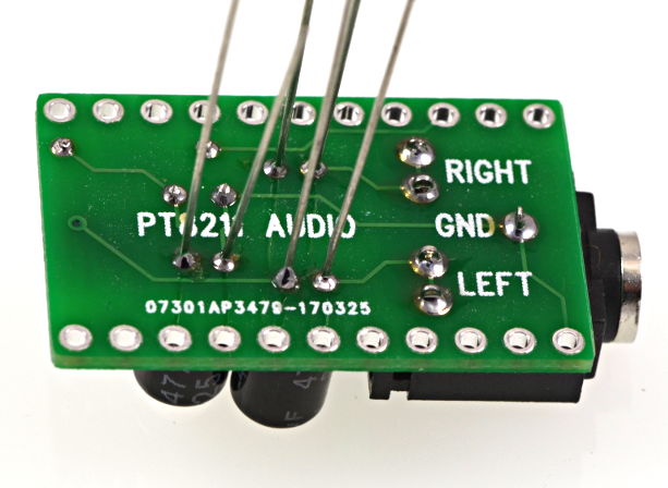
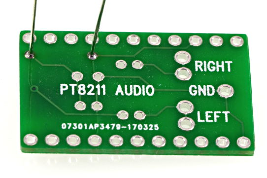
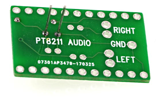
After all the parts are soldered, it's time to decide how your PT8211 board will connect with Teensy. In these photos, ordinary pins were soldered to the PT8211 board. You could choose to instead solder sockets to the PT8211, or use the double insulator pins to permanently join the two boards together.
While soldering, use a breadboard or another already-soldered board to slight the pins or sockets properly. After soldering, adjusting the direction is almost impossible.
Then join your assembled PT8211 shield to your Teensy 3.2, 3.5 or 3.6. The audio connector is placed above Teensy's USB connector. The PT8211 covers 22 of the 28 pins on Teensy 3.2, or 22 of the 48 pins on Teensy 3.5 & 3.6.
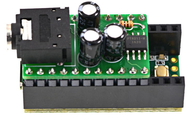
We do not recommend wires between Teensy and the PT8211. If wires are used, they should be kept short, especially ground. Teensy uses 4X oversampling on the stereo 44.1 kHz 16 bit data, so the data rate is very high. Lengthy wires between these boards are likely to cause trouble.
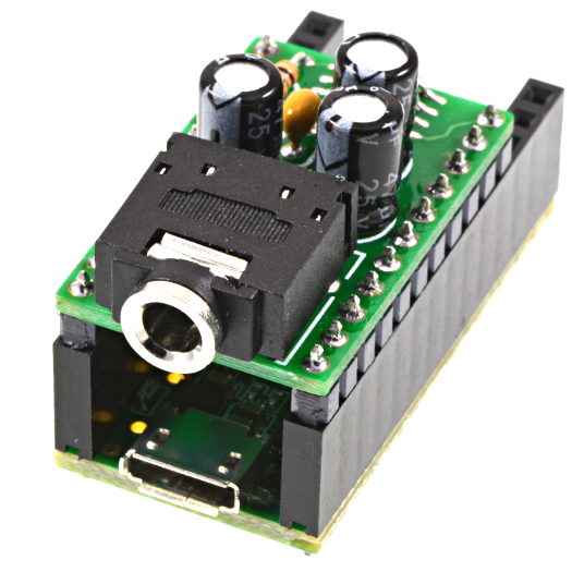
The completed assembly should look liks this:
Using PT8211 From The Audio Design Tool
Most audio library examples and the audio library tutorial use the I2S object to send to the Audio Shield. For example, here is the design from Part 2-2 of the tutorial.
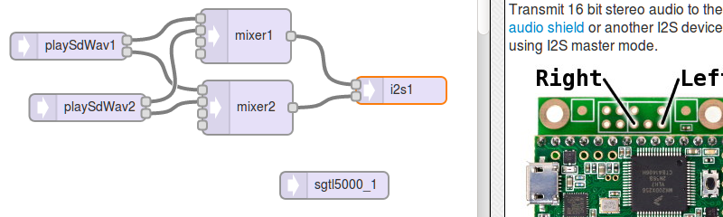
To convert this to PT8211, just delete the i2s1 output object and put a pt8211_1 object in its place. Redraw the 2 connections. Also delete the sgtl5000_1 object, since the PT8211 chip has no special control object.
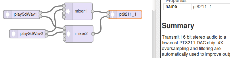
If you have code using the sgtl5000_1 object, just delete those lines. The PT8211 has no special adjustments like volume. It simply converts digital data to analog signals.
Modifying Existing Code For PT8211
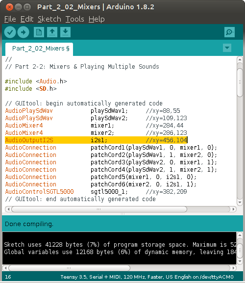
You can also easily convert existing code to use PT8211. Look for AudioOutputI2S.
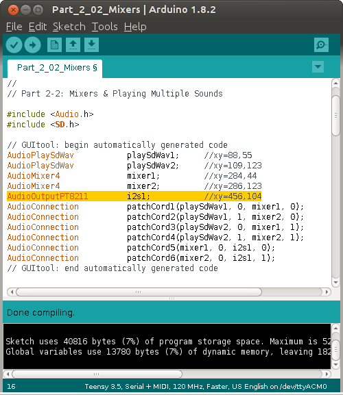
Simply change AudioOutputI2S to AudioOutputPT8211. Also delete any AudioControlSGTL5000 object.
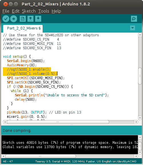
Programs originally writting to use AudioControlSGTL5000 will have lines you need to delete or comment out. In this case, the sgtl5000_1.enable() and sgtl5000_1.volume(0.5) are removed.
Using PT8211 Without Audio Library
PT8211 is a simple DAC which can be used just sending a pair of 16 bit numbers. PT8211 does not contain oversampling noise shaping filters or other complex signal processing which would require steady sample rate. It is possible to use as a simple DAC.The output voltage spans approximately 1.6 volts, centered between GND and 3.3V power. For DC coupled applications where you want numerical input 0 to give 0 volts DC, you will need an opamp circuit to shift the signal to ground. Calibration of the offset voltage with a trim pot or numerical adjustment in software may be needed.
Technical Details
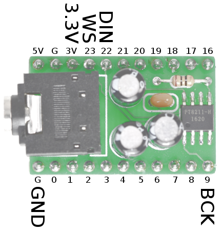
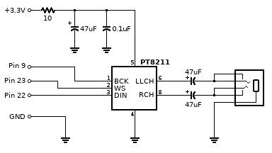
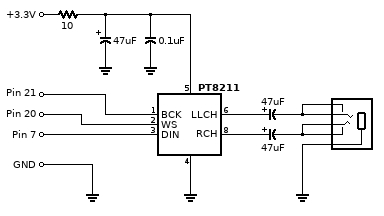
Signal     Teensy 3.x   Teensy 4.x   PT8211 Pin
------     ----------   ----------   ----------
 BCK            9           21           1
 DIN           22            7           3
 WS            23           20           2
 +3.3V       3.3V         3.3V           5
 GND          GND          GND           4
Teensy 3 Version
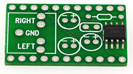
Teensy 4 Version

More details about the PCB are at this OSH Park page.