Tlc5940 Library
Tlc5940, by Alex Leone, interfaces with one of more TLC5940 chips from Texas Instruments. Though expensive, each chip provides 16 PWM outputs with 12 bit resolution, and built in current limiting for directly driving LEDs without resistors.
| Download: |
Included with the Teensyduino Installer Latest Developments on Github |
Tlc5940 works on Teensy 4.1, Teensy 4.0, Teensy 3.6, Teensy 3.5, Teensy 3.2, Teensy 3.1, Teensy 3.0, Teensy 2.0, Teensy++ 2.0, and Teensy++ 1.0.
Tlc5940 does not support Teensy LC or Teensy 1.0. The special servo motor mode (tlc_servo.h) only works on Teensy++ 2.0, and Teensy++ 1.0.
A special TLC5940 library with multiplexing and temporal dithering for Teensy 4.0 was shared on the forum by stereodan.
Hardware Requirements
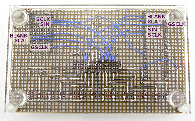
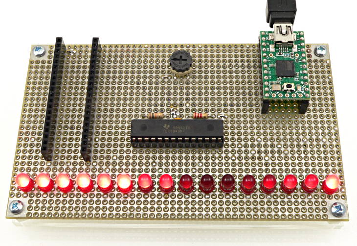 Tlc5940 test board. Wiring details shown below |
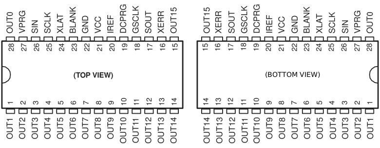
The TLC5940 chip (PDF) requires only 2 resistors and connects to Teensy using 5 signals.
| Signal | TLC5940 Pin | Teensy 4.x Pin | Teensy 3.x Pin | Teensy 2.0 Pin | Teensy++ 1.0 Pin | Teensy++ 2.0 Pin |
|---|---|---|---|---|---|---|
| GSCLK | 18 | 5 | 5 | 9 | 1 | 1 |
| BLANK* | 23 | 2 | 4 | 15 | 26 | 26 |
| XLAT | 24 | 3 | 3 | 14 | 25 | 25 |
| SCLK** | 25 | 7 | 7 | 1 | 21 | 21 |
| SIN | 26 | 6 | 6 | 2 | 22 | 22 |
| VPRG, GND | 27, 22 | Connect to GND | ||||
| DCPRG, VCC | 19, 21 | Connect to +5V | ||||
| IREF | 20 | Connect 2.2K resistor to GND | ||||
| Must be output mode | - | - | - | 0 | 20 | 20 |
| Unusable as PWM | - | - | - | 4 | 24, 27 | 24, 27 |
* The BLANK pin should have a 10K resistor connected to +5V (with Teensy 2) or +3.3V (with Teensy 3 or 4), to prevent the LEDs from lighting during programming or as Teensy boots.
** The SCLK pin is sensitive to signal overshoot. When long wires are used, especially with Teensy 4.x, you may need to add a resistor between Teensy and the SCLK wire.
Several TLC5940 chips may be used. The SOUT signal (pin 17) of each connects to the SIN (pin 26) of the previous chip, and GSCLK, BLANK, XLAT, SCLK are connected in common to all chips.
Example Programs
Tlc5940 includes several examples, available from the File > Examples menu.File > Examples > Tlc5940 > BasicUse
File > Examples > Tlc5940 > Fades
Peripherals Used
Tlc5940 uses the SPI port and 2 timers. The MISO pin is not used. The SS pin may only be used as an output. Timer1 and Timer2 are used on Teensy++. On Teensy, Timer1 and Timer3 are used. Some PWM pins associated with these timers are either used by the library. The others may be used as input or output, but not as PWM (analogWrite).Wiring and Pinout Info
 |
 |
Details
For more details, please refer to the official Tlc5940 page, or this older page.
For development on Tlc5940 for Teensy, please refer to this Github repository:
https://github.com/PaulStoffregen/Tlc5940