Matrix & Sprite Libraries
The Matrix library allows you to control a large number of LEDs, with easy-to-use (but expensive) MAX7219 chips. Sprite is used with Matrix, to draw shapes.Download: Matrix_Sprite.zip (updated for Arduino 1.0 & later)
Matrix and Sprite have been tested with Teensy 2.0, Teensy++ 2.0 and Teensy 3.0.
Hardware Requirements
Matrix uses one or more MAX7219 chips, with a grid of LEDs connected.
The grid can be only 8 LEDs in height, but the width may be any multiple of 8 by using multiple MAX7219 chips. Matrix requires non-obvious connections, explained below.
Basic Usage, Pixels Only
Matrix myLeds = Matrix(DIN, CLK, LOAD, numChips);Create an instance of the Matrix object, using a name of your choice. DIN, CLK and LOAD are the pin numbers where those signals are connected. You could create multiple object if you have connected multiple, separately wired MAX7219 chips.
myLeds.clear();Clear the entire display.
myLeds.setBrightness(15);Set the display brightness, from 0 to 15 (brightest).
myLeds.write(x, y, value);Change a single pixel. Value should be LOW for off, or HIGH for on.
Basic Usage, with Sprite
Sprite myIcon = Sprite(width, height, B11000, B11000, B11111, B11111);Create a sprite object. You may create as many sprites as you need, each with a unique name. The width should match the number of bits in each data value, and the height should match the number of data values.
myLeds.write(x, y, myIcon);Draw a sprite to the display.
Example Pixel-Based Program
This program turns on a single LED at a time, rapidly scanning line by line, left to right and top to bottom. If you have just completed wiring your LEDs, this simple test can help diagnose any problems.
#include <Sprite.h>  // Sprite before Matrix
#include <Matrix.h>

const int numChips = 3;

//                   DIN, CLK, LOAD, #chips
Matrix myLeds = Matrix(16, 17, 18, numChips);

void setup() {
  myLeds.clear();
}

void loop() {
  byte x, y;

  // light one LED at a time, scanning left to right
  // and top to bottom... useful for testing the matrix
  for (y=0; y<8; y++) {
    for (x=0; x<(numChips * 8); x++) {
      myLeds.write(x, y, HIGH);
      delay(50);
      myLeds.write(x, y, LOW);
    }
  }
}
Example Sprite-Based Program
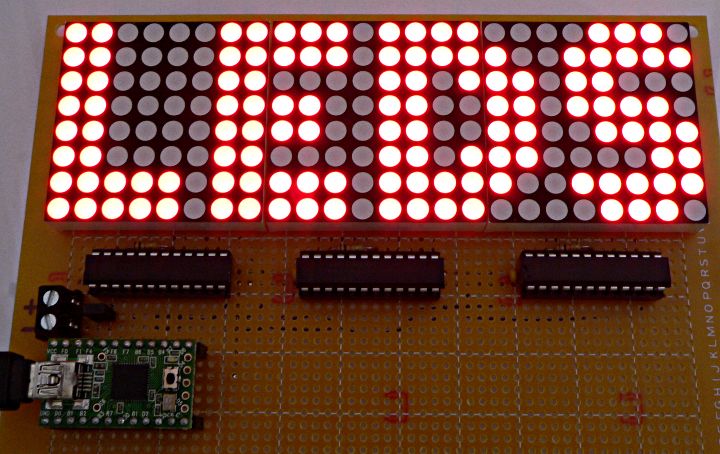
This example prints "LEDS" in large letters, as shown in the photo above.#include <Sprite.h> // Sprite before Matrix #include <Matrix.h> // DIN, CLK, LOAD, #chips Matrix myLeds = Matrix(16, 17, 18, 3); Sprite letter_L = Sprite(5, 8, B11000, B11000, B11000, B11000, B11000, B11000, B11111, B11111 ); Sprite letter_E = Sprite(5, 8, B11111, B11111, B11000, B11110, B11110, B11000, B11111, B11111 ); Sprite letter_D = Sprite(6, 8, B111100, B111110, B110111, B110011, B110011, B110111, B111110, B111100 ); Sprite letter_S = Sprite(5, 8, B01110, B11111, B11000, B11110, B01111, B00011, B11111, B01110 ); void setup() { myLeds.clear(); myLeds.setBrightness(4); myLeds.write(0, 0, letter_L); myLeds.write(6, 0, letter_E); myLeds.write(12, 0, letter_D); myLeds.write(19, 0, letter_S); } void loop() { }
MAX7219 Connections for Matrix
Matrix requires non-obvious connections to the MAX7219 chip. The chip's datasheet won't help much, because it uses 7-segment display names. Here is a MAX7219 pin diagram with the Matrix-specific signal names:
A 10K resistor should be connected between ISET and +5 volts.
The 64 LEDs are connected in a simple matrix arrangement.
If you have a pre-wired display block, like the 3 used in the photo above, make sure you orient them so the anodes are the X axis signals and the cathodes are the Y axis signals. Desoldering them to rotate 90 degrees is not fun!
Using Multiple MAX7219 Chips
Each MAX7219 chip controls 64 LEDs. You can chain multiple chips to form a wide matrix, but the height supported by the Matrix library is always only 8.The CLK and LOAD signals are connected to all chips. Only one chip receives data from the Teensy on its DIN pin. It's DOUT pin chains to the next chip's DIN pin, and so on.
Beware, the Matrix library wants Teensy to connect to the last chip, and the DOUT-to-DIN chain connects from right to left. That seems backwards, but if you wire Teensy to DIN on the left-most chip as might seem intuitive, your display will end up with groups of 8 instead of one nice, continuous X-axis coordinates.
Power Consumption
With a 10K resistor on the ISET pin, each LED uses approximately 50 mA with a duty cycle of 1/8th, for an average current of 6.25 mA per LED. When all 8 LEDs in a column are on, and the intensity set to maximum, the total current is 400 mA while the MAX7219 drives that column. If all 64 LEDs are on, the current will be a continuous 400 mA.USB can provide 500 mA from a PC or powered hub, but only 100 mA from an unpowered hub.
For a large matrix, external power will probably be needed. For example, the 24x8 matrix above can consume 1.2 amps when all LEDs are on at maximum intensity!